设计简介
摘
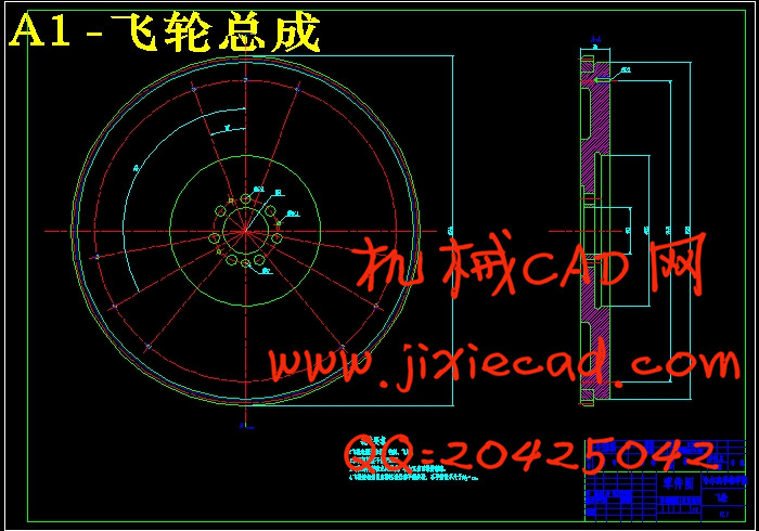
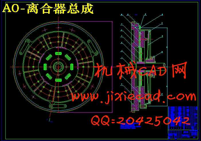
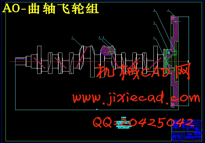
为了更好的解决发动机曲轴扭震等问题,本设计以上柴6CL320-2的相关数据作为参照,对235 直列六缸柴油机飞轮进行了惯量计算、结构设计、强度校核、离合器匹配,并对曲轴飞轮 组进行了有关运动学和动力学的理论分析与计算机仿真分析。
飞轮是一个转动惯量很大的圆盘,其主要功用是将在作功行程中传输给曲轴的功的一部分储存起来,用以在其他行程中克服阻力,带动曲轴连杆机构越过上、下止点,保证曲轴的旋转角速度输出转矩尽可能均匀,并使发动机有可能克服短时间的超过载;此外,在结构上飞轮又往往用作汽车传动系统中的摩擦离合器的驱动件。
关键词:飞轮 惯量计算 结构设计 离合器 运动仿真
Abstract
In order to better solve the engine crankshaft earthquake such issues, the design CL320-2 6 above wood of related data as a reference, to 235 kw in-line six diesel engine flywheel the inertia computation, structure design, intensity, clutch matching, and of crankshaft fly wheel about kinematics and dynamics theory analysis and computer simulation analysis.
The flywheel is a rotating inertia big disc, its main function is to do work in transmission of the trip to the crankshaft part of the power stored up, in other tour to overcome resistance, drive the crankshaft linkage mechanism, the check point across, guarantee of the crankshaft angular velocity output torque evenly as much as possible, and make the engine may overcome more than in the short time; In addition, on the structure of the flywheel and often used in automobile transmission system of friction clutch of driving part.
Key words: The flywheel; Inertia computation; Structure design; Clutch; Motion simulation
目 录
摘要 I
Abstract II
第1章 绪论 1
1.1 选题目的、意义 1
1.2 发动机飞轮国内外研究现状 2
1.3 曲轴系统的扭转振动 3
1.3.1 扭转振动的基本概念 3
1.3.2 扭转震动的消减措施 4
1.4 汽车离合器结构的发展 5
1.5 飞轮设计方法 6
1.6 主要研究内容 8
第2章 飞轮转动惯量的确定 9
2.1 飞轮转动惯量计算方法介绍 9
2.1.1 转动惯量的切向力方法 9
2.1.2 飞轮转动惯量的能量法 11
2.2 柴油机曲轴的旋转不均匀度 15
15
2.3 飞轮转动惯量 计算 17
计算 17
2.3.1飞转的作用 17
2.4 本章小结 20
第3章 飞轮结构设计 21
3.1 飞轮结构简介 21
3.2 飞轮材料选取 22
3.3 飞轮尺寸确定 23
3.3.1 飞轮基本结构形式 23
3.3.2 方案一:平板型飞轮 24
3.3.3 方案二:盆型飞轮 27
3.3.4 方案一与方案二对比 29
3.4本章小结 29
第4章 匹配离合器设计 30
4.1 离合器功用及设计要求 30
4.1.1 离合器的功用 30
4.1.2 对摩擦离合器的基本性能要求 30
4.1.3 膜片弹簧离合器概述 31
4.2 离合器结构设计 31
4.2.1 离合器的容量参数的计算 31
4.2.2 从动盘零件的结构选型和设计 33
4.2.3 压盘设计 35
4.2.4 离合器盖设计 35
4.3 本章小结 36
第5章 曲轴飞轮组零件创建与机构运动分析 37
5.1 CATIA软件简介 37
5.2 连杆的创建 37
5.2.1 连杆的特点分析 37
5.2.2 连杆的建模思路 37
5.3 活塞的创建 38
5.3.1 活塞的特点分析 38
5.3.2 活塞的建模思路 39
5.4 曲轴的创建 39
5.4.1 曲轴的特点分析 39
5.4.2 曲轴的建模思路 40
5.5 曲轴飞轮组运动分析 40
5.5.1 定义曲轴、连杆、活塞及活塞销的运动连接 40
5.5.2 设置曲轴与机座、活塞与活塞缸套之间的运动连接 43
5.5.3 模拟仿真 44
5.5.4运动分析 44
5.6 本章小结 47
结论 48
参考文献 49
致谢 50
为了更好的解决发动机曲轴扭震等问题,本设计以上柴6CL320-2的相关数据作为参照,对235
飞轮是一个转动惯量很大的圆盘,其主要功用是将在作功行程中传输给曲轴的功的一部分储存起来,用以在其他行程中克服阻力,带动曲轴连杆机构越过上、下止点,保证曲轴的旋转角速度输出转矩尽可能均匀,并使发动机有可能克服短时间的超过载;此外,在结构上飞轮又往往用作汽车传动系统中的摩擦离合器的驱动件。
关键词:飞轮 惯量计算 结构设计 离合器 运动仿真
Abstract
In order to better solve the engine crankshaft earthquake such issues, the design CL320-2 6 above wood of related data as a reference, to 235 kw in-line six diesel engine flywheel the inertia computation, structure design, intensity, clutch matching, and of crankshaft fly wheel about kinematics and dynamics theory analysis and computer simulation analysis.
The flywheel is a rotating inertia big disc, its main function is to do work in transmission of the trip to the crankshaft part of the power stored up, in other tour to overcome resistance, drive the crankshaft linkage mechanism, the check point across, guarantee of the crankshaft angular velocity output torque evenly as much as possible, and make the engine may overcome more than in the short time; In addition, on the structure of the flywheel and often used in automobile transmission system of friction clutch of driving part.
Key words: The flywheel; Inertia computation; Structure design; Clutch; Motion simulation
目 录
摘要 I
Abstract II
第1章 绪论 1
1.1 选题目的、意义 1
1.2 发动机飞轮国内外研究现状 2
1.3 曲轴系统的扭转振动 3
1.3.1 扭转振动的基本概念 3
1.3.2 扭转震动的消减措施 4
1.4 汽车离合器结构的发展 5
1.5 飞轮设计方法 6
1.6 主要研究内容 8
第2章 飞轮转动惯量的确定 9
2.1 飞轮转动惯量计算方法介绍 9
2.1.1 转动惯量的切向力方法 9
2.1.2 飞轮转动惯量的能量法 11
2.2 柴油机曲轴的旋转不均匀度
2.3 飞轮转动惯量
2.3.1飞转的作用 17
2.4 本章小结 20
第3章 飞轮结构设计 21
3.1 飞轮结构简介 21
3.2 飞轮材料选取 22
3.3 飞轮尺寸确定 23
3.3.1 飞轮基本结构形式 23
3.3.2 方案一:平板型飞轮 24
3.3.3 方案二:盆型飞轮 27
3.3.4 方案一与方案二对比 29
3.4本章小结 29
第4章 匹配离合器设计 30
4.1 离合器功用及设计要求 30
4.1.1 离合器的功用 30
4.1.2 对摩擦离合器的基本性能要求 30
4.1.3 膜片弹簧离合器概述 31
4.2 离合器结构设计 31
4.2.1 离合器的容量参数的计算 31
4.2.2 从动盘零件的结构选型和设计 33
4.2.3 压盘设计 35
4.2.4 离合器盖设计 35
4.3 本章小结 36
第5章 曲轴飞轮组零件创建与机构运动分析 37
5.1 CATIA软件简介 37
5.2 连杆的创建 37
5.2.1 连杆的特点分析 37
5.2.2 连杆的建模思路 37
5.3 活塞的创建 38
5.3.1 活塞的特点分析 38
5.3.2 活塞的建模思路 39
5.4 曲轴的创建 39
5.4.1 曲轴的特点分析 39
5.4.2 曲轴的建模思路 40
5.5 曲轴飞轮组运动分析 40
5.5.1 定义曲轴、连杆、活塞及活塞销的运动连接 40
5.5.2 设置曲轴与机座、活塞与活塞缸套之间的运动连接 43
5.5.3 模拟仿真 44
5.5.4运动分析 44
5.6 本章小结 47
结论 48
参考文献 49
致谢 50


