设计简介
摘 要
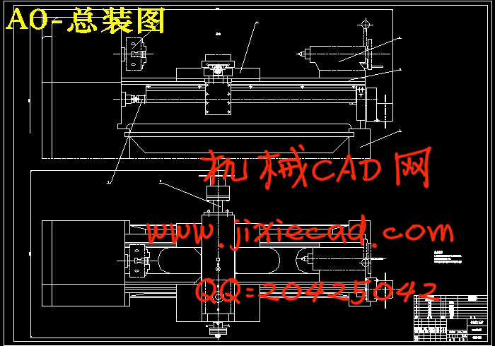
针对现有常规C620普遍车床的缺点提出数控改装方案和单片机系统设计,提高加工精度和扩大机床使用范围,并提高生产率。本论文说明了普通车床的数控化改造的设计过程,较详尽地介绍了C620机械改造部分的设计及数控系统部分的设计。采用以8031为CPU的控制系统对信号进行处理,由I/O接口输出步进脉冲,经一级齿轮传动减速后,带动滚动丝杠转动,从而实现纵向、横向的进给运动。
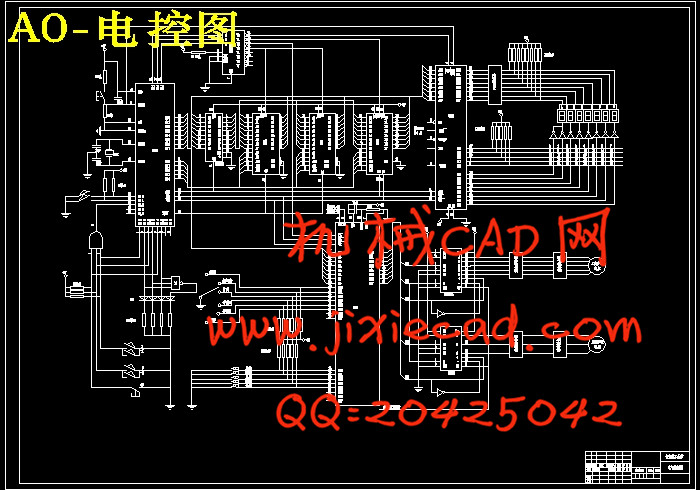
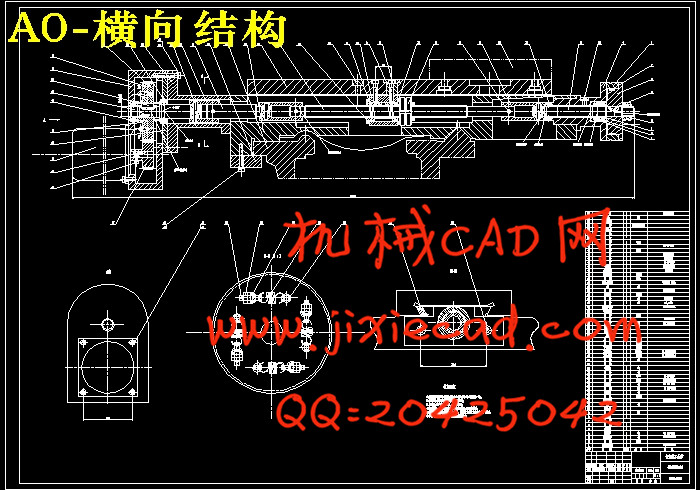
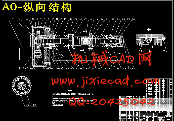
改造过程如下:(1)机械部分的改造,包括纵向进给方向的改造和横向进给方向的改造。主要包括对滚珠丝杠螺母副及反应式步进电机的计算选择及纵向、横向机构装配图方案的制定。(2)电气控制部分的设计,主要包括MCS-51系列单片机及扩展芯片的选用和电气控制图的设计。
关键词:数控,单片机,步进电机,滚珠丝杠,改造
ABSTRACT
To remedy the defects of ordinary lather C620, a design of data processing system and its single chip microcomputer system program is put forward to raise the processing precision and extend the machine’s usage, and to improve production rate。This paper presents the process of designing numerical control reform,and explicitly introduces the design of mechanical and numerical control system reforms。We adopt control system which has 8031 as cpu to cope with the signal,and output the step pulse through the I/O interface。After transmitting and slowing down by force 1 gear, the step pulses drive the leading screw to roll。Thus achieve the vertical movement and the crosswise movement。
Reform process as follows:(1)The reformation of machine part, include to enter lengthways to the reformation of the direction with horizontal enter to direction of reformation. Mainly include to roll the ball screw shaft nut and the calculation choice of reaction stepping motor and the establishment of lengthways, horizontal organization assemble diagram project. (2)The reformation of electricity part, mainly include the choice of MCS-51 family single-chip and expand chip and the design of electric control chart.
Key words : numerical control ,single-chip ,stepping motor , ball screw shaft ,reform
目 录
摘 要 Ⅰ
Abstract(英文摘要) Ⅱ
目 录 Ⅲ
引 言 1
第一章 总体方案的设计 3
1.1 设计任务 3
1.2 总体方案的论证 3
1.2.1 机械部分的改造设计 3
1.2.2 伺服进给系统的改造设计 4
1.2.3数控系统的硬件电路设计 4
1.3 总体方案的确定 5
第二章 机械部分的改造设计 6
2.1 纵向进给系统的改造设计 6
2.1.1 纵向滚珠丝杠副的选用 6
2.1.1.1 确定系统脉冲当量 7
2.1.1.2 车削力的计算 7
2.1.1.3滚珠丝杠副的设计、计算和选型 7
2.1.2 步进电机的选用 11
2.1.1.1 脉冲量的计算 11
2.1.1.2 等效负载转矩的计算 11
2.1.1.3 等效转动惯量的计算 12
2.1.1.4 步进电机型号的选择 12
2.2 横向进给系统得改造设计 13
2.2.1 横向滚珠丝杠副的选用 13
2.2.1.1 确定系统的脉冲当量 13
2.2.1.2 车削力的计算 13
2.2.1.3滚珠丝杠副的设计、计算和选型 14
2.2.2 横向步进电机的选用 17
2.2.2.1 脉冲量的计算 17
2.2.2.2 等效负载转矩的计算 17
2.2.2.3 等效转动惯量的计算 18
2.2.2.4 步进电机型号的选择 18
2.3 齿轮传动间隙的调整 19
第三章 电气控制部分的设计 22
3.1 单片机的选择 22
3.2 步进电机的驱动 23
3.2.1 环形脉冲分配器的选择 24
3.2.2 功率放大器的选用 25
3.3 步进电机的微机控制 28
结论 30
致谢31
2.2.2 横向步进电机的选用 17
2.2.2.1 脉冲量的计算 17
2.2.2.2 等效负载转矩的计算 17
2.2.2.3 等效转动惯量的计算 18
2.2.2.4 步进电机型号的选择 18
2.3 齿轮传动间隙的调整 19
第三章 电气控制部分的设计 22
3.1 单片机的选择 22
3.2 步进电机的驱动 23
3.2.1 环形脉冲分配器的选择 24
3.2.2 功率放大器的选用 25
3.3 步进电机的微机控制 28
结论 30
致谢31
参考文献 32


