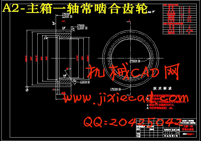
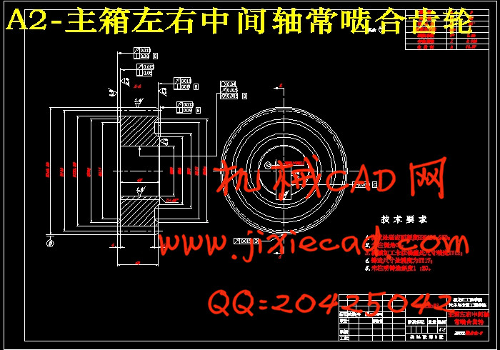
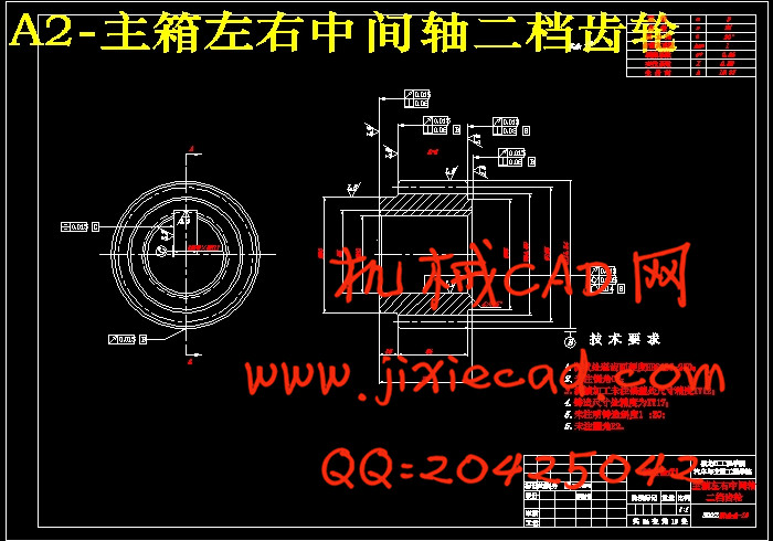
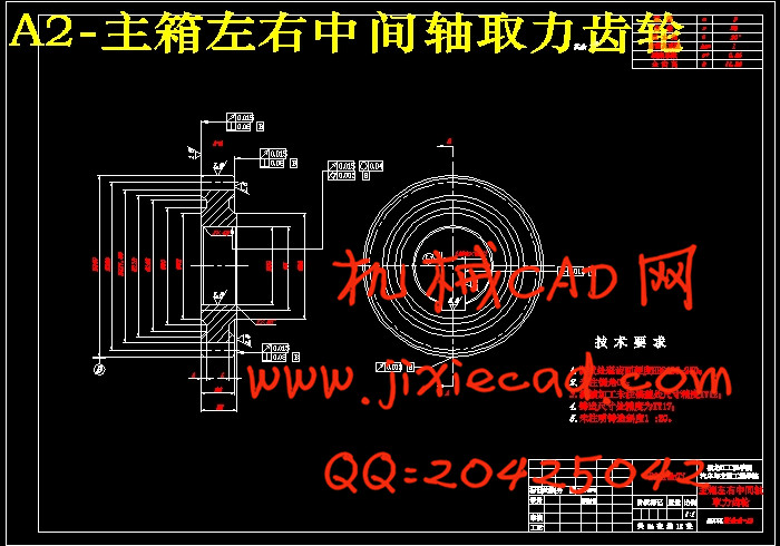
设计简介
摘 要
变速器用来改变发动机传到驱动轮上的转矩和转速,是汽车总成部件中的重要组成部分,是主要的传动系统。变速器的结构要求对汽车的动力性、燃料经济性、换档操纵的可靠性与轻便性、传动平稳性与效率等都有直接的影响。
CA10TA190M变速器是一款双中间轴重型汽车专用变速器。主副箱变速箱组合设计,主箱变速箱为手动操纵,副箱变速箱为气动操纵,具有10个前进档,2个倒档。该变速箱使用功率范围260~420马力之间的重型车用发动机,广泛适应中国目前的道路状况和运输情况。
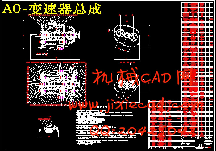
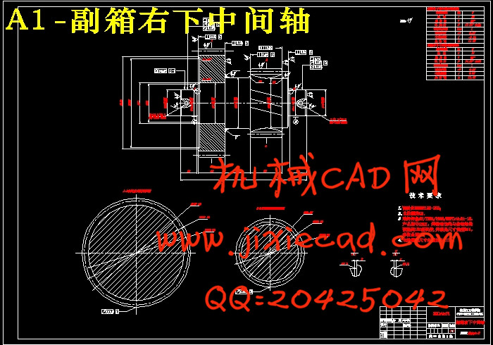
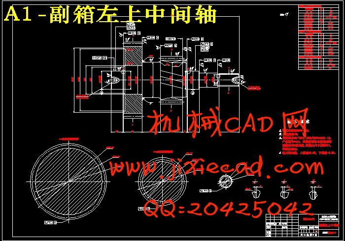
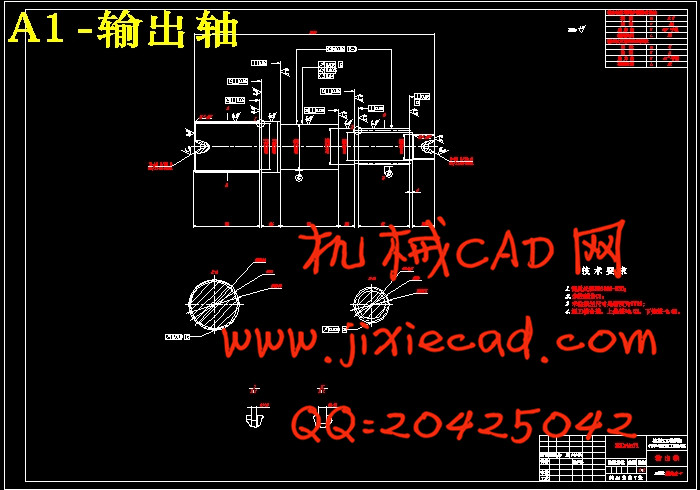
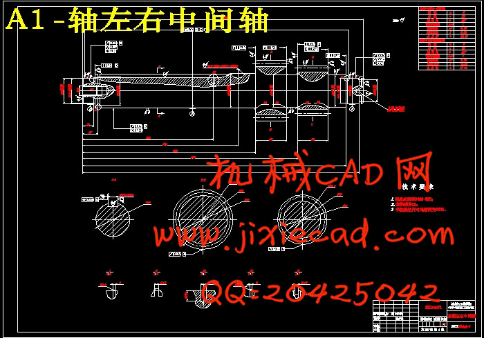
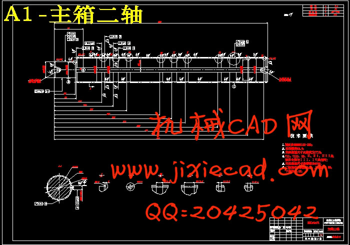
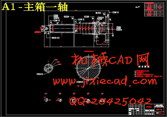
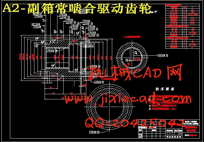
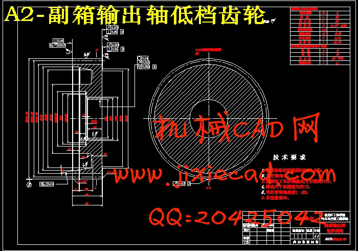
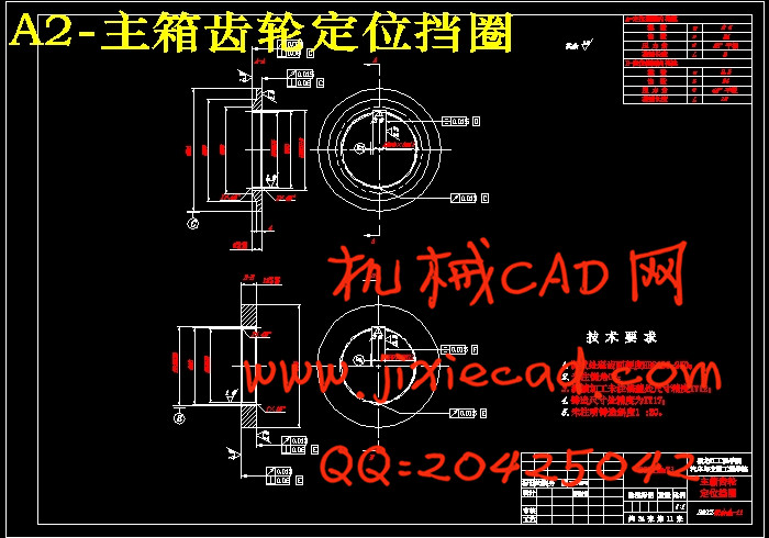
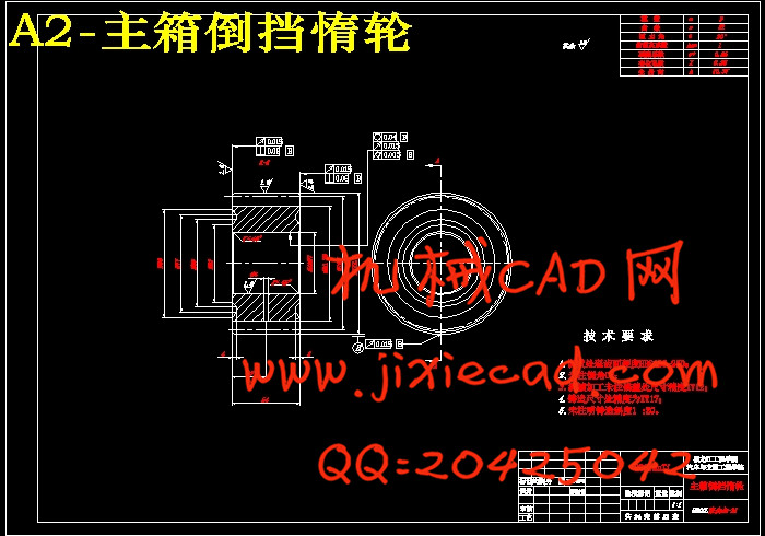
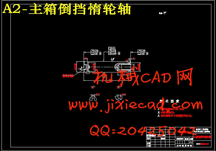
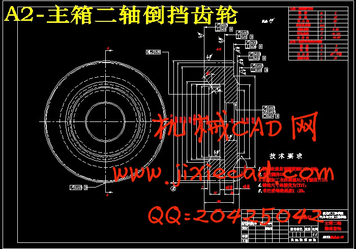
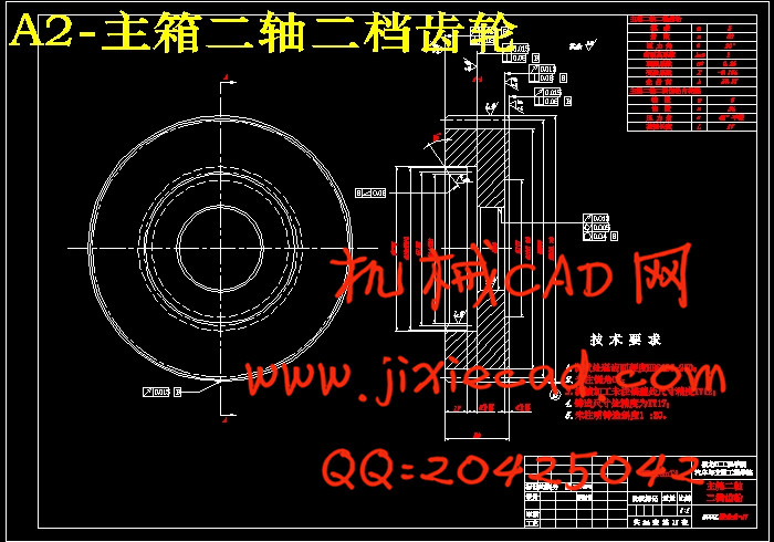
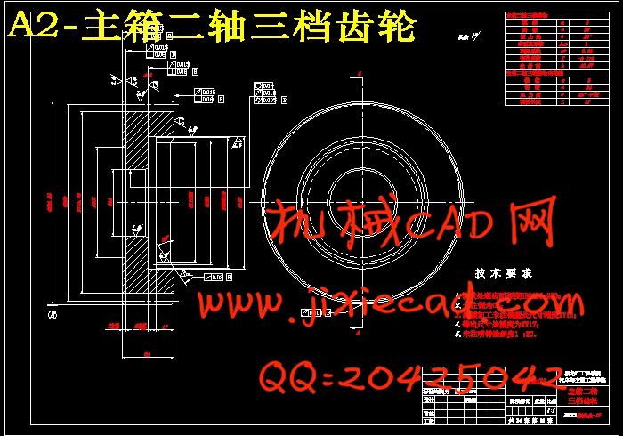
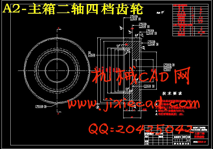
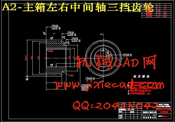
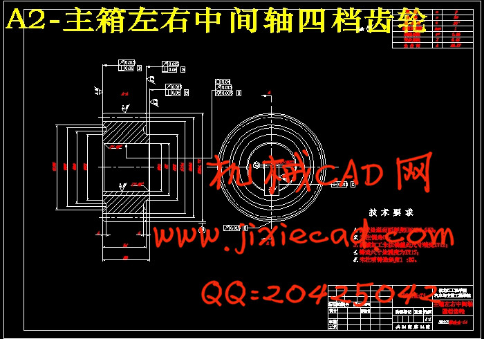
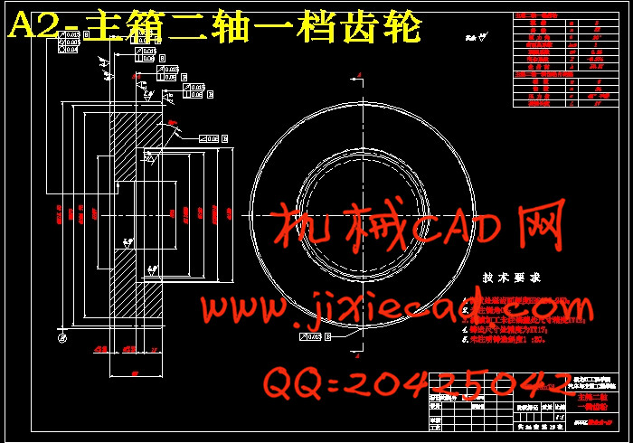
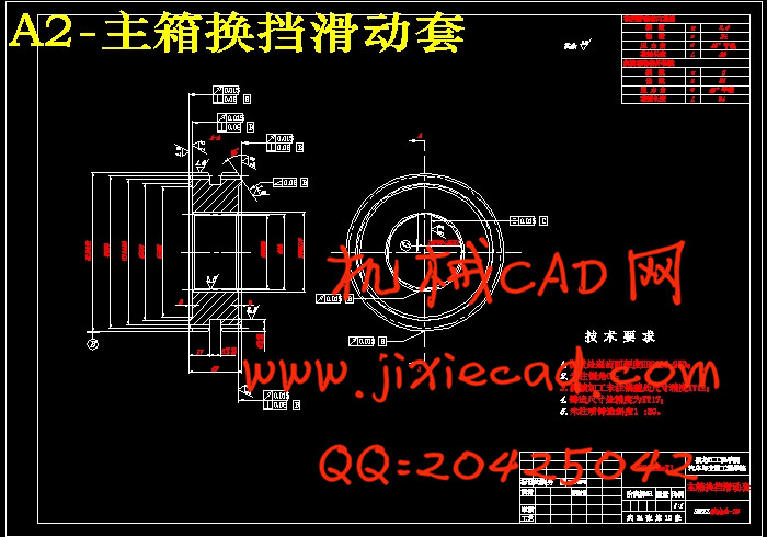
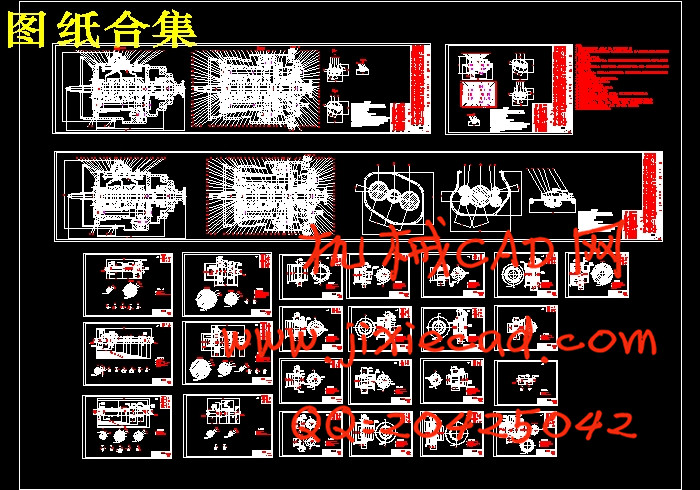
本设计研究了CA10TA190M双中间轴十档手动变速器。其主要目的是以机械设计基础、工程力学、机械精度设计与监测基础、金属工艺学、汽车构造、汽车设计、汽车制造工艺学等课程为依托,并运用AutoCAD、PRO/E、ANSYS设计校核软件对该变速箱进行仿形设计。本设计的主要成果:深入了解了国内外各大重型商用车组合式变速器生产厂家的研发现状;进行了该装配工艺的分析;进行了该变速箱的总体布置并确定了传动方案;完成了主箱一轴总成、主箱二轴总成,主箱左右中间轴总成、主箱换挡滑动套、主箱换挡操纵机构、副箱左右中间轴总成、副箱输出轴总成的设计与校核;进行了该变速箱的箱体设计;进行了该变速箱性能分析。主要包括变速器对整车动力性经济性影响的计算,换挡时机与车速的匹配;对该变速器主副箱各轴进行了ANSYS静力学分析;绘制了该变速箱的1张装配图与23张零件图;通过这些设计成果,基本完成了CA10TA190M双中间轴十档手动变速器的仿形设计。
关键词:CA10TA190M;变速器;双中间轴;设计
ABSTRACT
Transmission to change the engine reached on the driving wheel torque and speed, Automotive transmission parts in the automobile assembly of an important part of the main drive system. Transmission of the power structure of the vehicle, economy, manipulation of the reliability and portability, the smooth drive and have a direct impact on efficiency.
CA10TA190M transmission is a paragraph of heavy duty truck special twin countershaft transmission. Lord vice box transmissionassembly design, Lord box transmissionmanually manipulation, vice box for the pneumatic manoeuvring, with transmission10 forward gears, 2 in reverse. The trasmissionuse power range between 260 ~ 420 horsepower engine, widely &heavy vehicles to China's current road conditions and transportation situation.
This design research CA10TA190M Twin Countershaft Transmission. Its main purpose is mechanical design basis, engineering mechanics, mechanical precision design and monitoring foundation, metal technology, automobile structure, automobile design, automobile manufacture technology, and use relying on course to AutoCAD, PRO/E, ANSYS software in the transmissiondesign check for imitation shape design. The design of the main achievements: In-depth understanding of the major domestic and foreign heavy commercial combined-type transmission manufacturer's r&d status; The transmission assembly process analysis; The overall layout of the transmission and determine the transmission scheme; Completed a shaft assembly, Lord box second shaft assembly, Lord box about Lord box, Lord box Countershaft assembly, Lord box of shift sliding shift operation, deputy box Countershaft assembly, deputy box around the output shaft assembly design and checking; Conducted this transmission cabinet design; The transmission properties were analyzed. Mainly includes the transmission, the influence on the economy of vehicle dynamic calculation, the shift timing and speed matching; Lord the vice box the axis ANSYS statics analysis; Painted this transmission assembly drawings of 1 card with 23 zhang parts graph; Through this design results, basic completed CA10TA190M twin manual shift transmission Countershaft ten imitation shape design.
Key words: CA10TA190M;Transmission;Twin Countershaft;Design
目 录
摘要 Ⅰ
Abstract Ⅱ
第1章 绪论 1
1.1 选题的目的依据和意义 1
1.1.1 选题的目的 1
1.1.2 选题的依据 1
1.1.3 选题的意义 4
1.2 重型商用车变速器的研究现状 4
1.2.1 国外重型商用车变速器的研究现状 4
1.2.2 国内重型商用车变速器的研究现状 5
1.3 设计的基本内容与解决的主要问题 9
1.3.1 设计的基本内容 9
1.3.2 设计解决的主要问题 9
第2章 车型参数的确定与校核 11
2.1 一汽解放J6车型参数 11
2.1.1 车型参数的确定 11
2.1.2 车桥参数的确定 14
2.2 车型技术参数校核 14
2.2.1 质量参数 14
2.2.2 轴距和轮距 15
2.2.3 轴荷分布 15
2.2.4 动力性参数 16
2.2.5 燃油经济性参数 16
2.2.6 最小转弯直径 17
2.2.7 通过性 17
2.2.8 操作稳定性 17
2.2.9 制动性 18
2.2.10 发动机最大功率与最大功率转速 18
2.2.11 发动机最大转矩与最大转矩转速 19
2.2.12 主减速比 19
2.3 本章小结 22
第3章 变速器的装配工艺性分析 23
3.1 变速器的装配工艺性分析 23
3.1.1 产品能分成若干个独立装配的单元 23
3.1.2 要有正确的装配基准 23
3.1.3 便于装配与拆卸 24
3.1.4 正确选择装配方法是尽量减少装配时的修配和机加工 25
3.2 本章小结 26
第4章 CA10TA190M双中间轴变速器的总体布置 27
4.1 CA10TA190M双中间轴变速器的结构特点 27
4.1.1 主副箱结构 27
4.1.2 换挡滑套与同步器 28
4.1.3 细高齿与“对齿” 29
4.1.5 润滑与密封 31
4.1.6 齿轮强度 31
4.1.7 操纵机构 31
4.1.8 取力形式 31
4.1.9 成本与寿命 31
4.2 CA10TA190M双中间轴变速器的工作原理和动力传递路线 32
4.2.1 CA10TA190M双中间轴变速器的工作原理 32
4.2.2 CA10TA190M双中间轴变速器的动力传递路线 34
4.3 CA10TA190M双中间轴变速器的装配 34
4.4 变速器传动机构分析和布置方案的设计 34
4.4.1 两轴式变速器和中间轴式变速器多中间轴式变速器的特点分析 35
4.4.2 变速器倒档布置方案分析确定 36
4.4.3 传动机构布置中齿轮安排的分析确定 37
4.5 变速器零部件结构方案分析确定 38
4.5.1 齿轮形式 38
4.5.2 变速器自动脱档机构形式分析确定 39
4.6 本章小结 40
第5章 变速器主要参数的确定 41
5.1 变速器档位数目及各档传动比 41
5.1.1 变速器档位数目的确定 41
5.1.2 变速器一档传动比的确定 41
5.1.3 变速器各档传动比的确定 43
5.2 变速器中心距的确定 48
5.3 变速器的外形尺寸 50
5.4 变速器的齿轮参数的确定 50
5.4.1 齿轮齿数 50
5.4.2 齿轮模数 51
5.4.3 齿形、压力角及螺旋角 54
5.4.4 齿宽 55
5.4.5 齿顶高系数 56
5.4.6 齿轮的修正 56
5.5 变速器各档齿轮齿数的分配 58
5.5.1 确定主箱一档齿轮副参数 60
5.5.2 确定主箱常啮合齿轮副参数 64
5.5.3 确定主箱二档齿轮副参数 67
5.5.4 确定主箱三档齿轮副参数 71
5.5.5 确定主箱四档齿轮副参数 74
5.5.6 确定主箱取力齿轮参数 77
5.5.7 确定主箱二轴倒档齿轮与惰轮传动副参数 78
5.5.8 确定主箱倒档惰轮与左右中间轴倒档齿轮副参数 82
5.5.9 确定副箱高档齿轮副参数 85
5.5.10 确定副箱低档齿轮副参数 89
5.6 精确计算主副箱各档传动比 94
5.7 主副箱各档齿轮几何参数 97
5.8 本章小结 97
第6章 变速器齿轮的设计及校核 98
6.1 齿轮的材料选择 98
6.1.1 齿轮坏损形式及防止措施 98
6.1.2 齿轮传动设计准则 100
6.1.3 齿轮的材料选择 100
6.2 计算主副箱各轴转矩 102
6.3 齿轮的强度计算 103
6.3.1 轮齿的弯曲应力 103
6.3.2 轮齿接触应力 106
6.3.3 主副箱各档齿轮的强度计算校核 107
6.4 计算主副箱各档齿轮的在啮合点处的受力 119
6.4.1 主箱一档齿轮受力 120
6.4.2 主箱二档齿轮受力 120
6.4.3 主箱三档齿轮受力 120
6.4.4 主箱四档齿轮受力 121
6.4.5 主箱常啮合齿轮受力 121
6.4.6 主箱倒档齿轮受力 122
6.4.7 主箱一档时副箱低档齿轮受力 123
6.4.8 主箱一档时副箱高档齿轮受力 123
6.4.9 变速器R2档时副箱低档齿轮受力 124
6.4.10 变速器R2档时副箱高档齿轮受力 124
6.5 本章小结 125
第7章 变速器主副箱各总成的设计 127
7.1 轴的设计 127
7.1.1 轴的功用及其设计要求 127
7.1.2 轴的结构设计 127
7.1.3 初步确定轴的尺寸 129
7.2 主副箱各轴尺寸设计 131
7.2.1 主副箱各轴总成详细尺寸 131
7.2.2 主副箱各轴总成轴段设计 131
7.3 计算主副箱各轴与齿轮的花键 134
7.3.1 花键的特点及应用 134
7.3.2 主副箱各轴花键的设计公式 135
7.3.3 计算主副箱各轴与齿轮渐开线花键 135
7.4 主副箱各轴总成校核 140
7.4.1 主箱一轴总成校核 140
7.4.2 主箱二轴总成校核 146
7.4.3 主箱左右中间轴总成校核 158
7.4.4 主箱倒档惰轮轴总成校核 167
7.4.5 副箱左右中间轴总成校核 171
7.4.6 副箱输出轴总成校核 179
7.5 本章小结 183
第8章 操纵机构和箱体的确定 184
8.1 换挡操纵机构概述 184
8.1.1 换挡操纵机构的功用 184
8.1.2 换挡操纵机构结构的设计要求 184
8.2 换档操纵机构零部件的选用 185
8.2.1 换挡位置图 185
8.2.2 变速器换档机构形式 185
8.3 变速器的操纵形式 188
8.3.1 直接操纵手动换挡变速器 188
8.3.2 远距离操纵手动换挡变速器 189
8.4 锁止装置 189
8.4.1 互锁装置 189
8.4.2 自锁装置 191
8.4.3 倒档锁装置 192
8.5 变速器箱体的设计 193
8.6 本章小结 194
第9章 变速器与整车匹配性计算 195
9.1 汽车动力性评价指标 195
9.1.1 汽车的最高车速 195
9.1.2 汽车的加速时间 195
9.1.3 汽车的最大爬坡度 195
9.2 汽车燃油经济性的评价指标 196
9.2.1 单位行驶里程的燃油消耗量 196
9.2.2 单位运输工作量的燃油消耗量 196
9.2.3 消耗单位燃油所行驶的里程 196
9.2.4 汽车燃油经济性的影响因素 196
9.2.5 变速器档数对燃油经济性的影响 197
9.3 汽车动力性计算 197
9.3.1 发动机功率—扭矩曲线 197
9.3.2 汽车速度—发动机转速曲线 197
9.3.3 汽车行驶驱动力图 198
9.3.4 汽行驶驱动力—行驶阻力图 198
9.3.5 加速性能曲线 199
9.3.6 最大驱动力与经济车速分析 200
9.4 换挡时机与发动机转速的匹配 200
9.4.1 车速与发动机转速之间的关系 200
9.4.2 两脚离合换挡方法举例 201
9.5 本章小结 203
第10章 主副箱各轴ANSYS静力学分析 204
10.1 有限元基本理论简介 204
10.2 有限元分析的基本步骤 205
10.2.1 一轴的ANSYS静力学分析 205
10.2.2 二轴的ANSYS静力学分析 209
10.2.3 主箱左右中间轴的ANSYS静力学分析 224
10.2.4 副箱左上中间轴的ANSYS静力学分析 228
10.2.5 副箱右下中间轴的ANSYS静力学分析 231
10.2.6 输出轴的ANSYS静力学分析 234
10.3 本章小结 237
结论 238
参考文献 240
致谢 243


