设计简介
摘
机械加工工艺规程是规定产品或零部件机械加工工艺过程和操作方法等的工艺文件。为能具体确切地说明工艺过程,一般将机械加工工艺过程分为工序、安装、工位、工步和走刀。而生产规模的大小、工艺水平的高低以及解决各种工艺问题的方法和手段都要通过机械加工工艺规程来体现。因此,机械加工工艺规程设计是一项重要而又严格的工作。一般包括以下步骤和内容:阅读装配图和零件图;工艺审查;熟悉或确定毛坯;拟定机械加工工艺路线;确定工艺装备(包括机床、夹具、刀具和量具等);确定各主要工序的技术要求和检验方法;确定各工序的加工余量、计算工序尺寸;确定切削用量;确定时间定额;填写工艺文件[1]。
夹具是一种装夹工件的工艺装备。它广泛地应用于机械制造过程的切削加工、热处理、装备、焊接和检测等工艺过程。在生产中具有很大的作用,具体表现在:保证加工质量;提高生产率;减轻劳动强度;扩大机床的工艺范围。机床夹具对工件进行安装(又称装夹)包括两层含义:一是把工件安放在机床工作台上或夹具中,使它和刀具之间有相对正确的位置,称为定位;二是将工件固定,使其在加工过程中保持定位位置不变,称为夹紧。
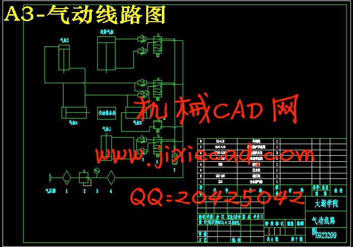
气动系统[2]的设计是设备控制与运行设计的重要内容。根据机电设备对液压、气压系统的具体要求,利用气动传动的基本原理,拟定合理的气动系统图。气压传动是利用空气压缩机将电动机或其他原动机输出的机械能转换为空气的压力能。在控制元件的控制和辅助元件的配合下,通过执行元件把空气能转换为机械能,从而完成直线或回转运动并对外做功。
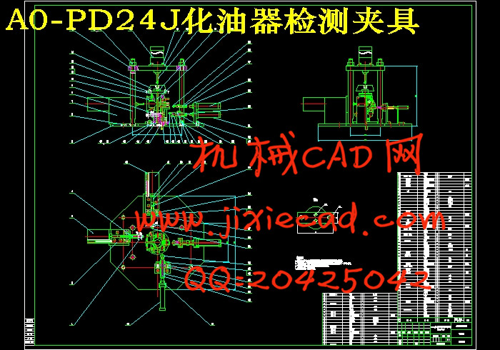
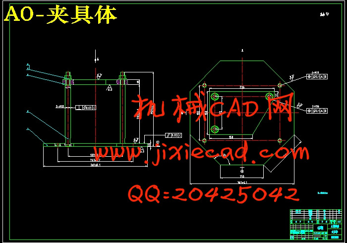
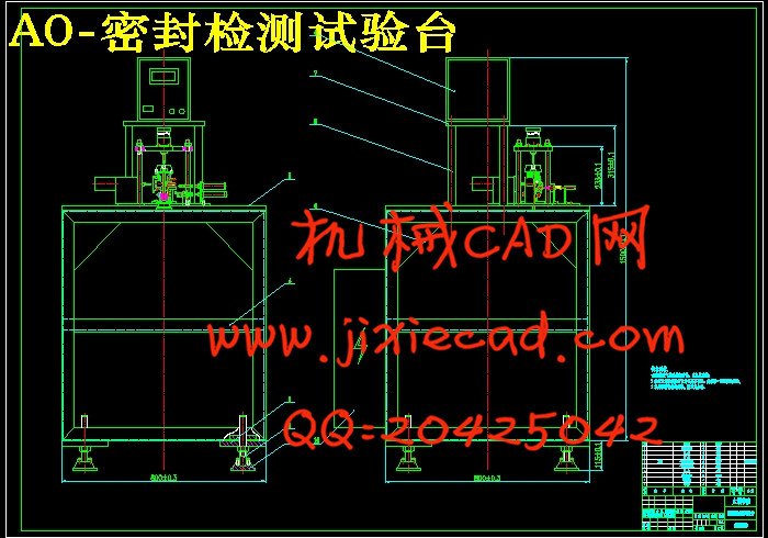
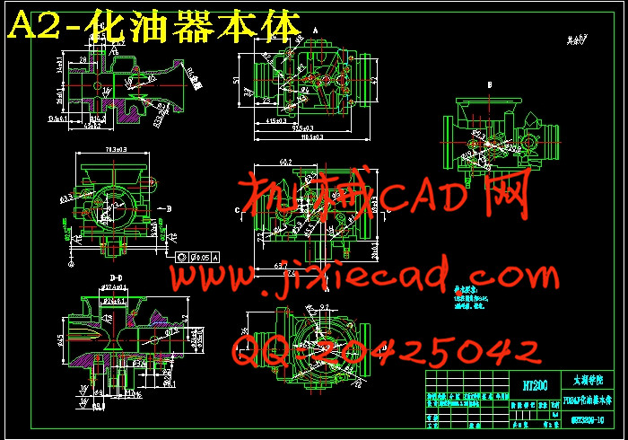
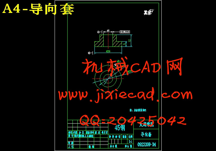
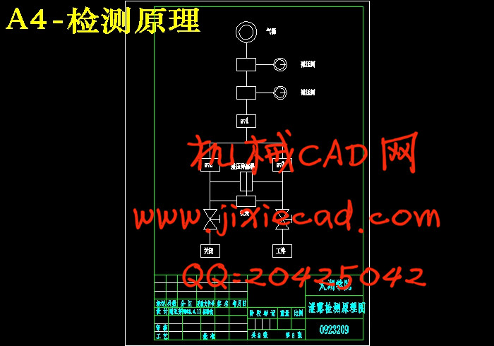
本次设计的课题是PD24J化油器怠速孔试密封设备设计,首先要对化油器本体进行分析,进行机械部分夹具的设计,包括夹具的定位误差分析和夹紧力的计算;其次是气动部分的设计,包括气动回路的设计和管道的计算;最终是电气部分PLC的设计,包括工作流程图和梯形图。
关键词:工艺规程;夹具;气动系统;夹紧力;PLC
Abstract
The machining process planning is the process of document products or parts machining process and method of operation. In order to exact description of process, the machining process is divided into process, installation, position, working step and walk the knife. While the production level, technology level and means to solve various technical problems are reflected by the machining process planning. Therefore, the machining process planning design is an important and strict working. Generally,it includes the following steps: reading assembly and parts drawings, process recviewing;being familiar with the blank or determining the blank, formulating the route of machining process, determination of process equipments (including machine tool, fixture tool,cutter and measuring tool), determination of the technical requirements of the main process and test methods, determination of machining allowance, the process calculation procedure dimensions, determination of the amount of cutting, determination of the time quota, filling the process documents.
Fixture is a device clamping workpiece. It is widely used in the manufacturing process of machining, heat treatment, welding equipment, and detection technology. It has a great role in the production, specifically manifested in: quality of assurance process, increasing of the rate of productivity, reducing the labor intensity, expanding the scope of technology of machine tool. Machine tool fixture installing on the workpiece (also called clamping) includes two meanings: one is that placing artifact in the workpiece worktable of a machine tool or fixture in order to make a relatively correct position between it and the tool called location. Another is that workpiece is fixed, so as to maintain position position unchanged in the process known as the clamp.
Design of the pneumatic system is an important content of equipment controlling and operation designing. According to the specific requirements of the electrical and mechanical equipment hydraulic, and the basic principle of transmission by gas,we can formulate reasonable pneumatic system diagram. Pneumatic drive can switch mechanical energy into air pressure by air compressor motor or other original motivation. With the help of the control elements and auxiliary components, it can switch air pressure into mechanical energy through the implementation of components,so as to complete the linear or rotary motion and external work.
The design topic is the design of PD24J carburetor idle hole test sealing equipment. Firstly,I must make the analysis to the carburetor body and design mechanical parts of fixture, including the calculation of positioning errors and the clamping force. Secondly,I should make the design of pneumatic parts, including the calculation of the pneumatic circuit and pipeline. The last one is that the design of electrical part of PLC, including the work flow diagram and ladder diagram.
Key words: Process specification; Fixture; Pneumatic; Clamping force; PLC
Abstract IV
目 录 V
1 绪论 1
1.1 本课题的研究内容和意义 1
1.2 国内外的发展概况 1
1.3 本课题应达到的要求 1
2 总体方案设计 2
2.1 本装置的主要组成部分 2
2.2 机械部分的作用及其设计原则 2
2.3 气动部分的功能 2
2.4 PLC部分的功能 3
3 机械部分的设计 4
3.1 定位基准的选择 4
3.1.1 粗基准的选择 4
3.1.2 精基准的选择 4
3.2 零件表面加工工序的选择 4
3.2.1 工序顺序的安排原则 4
3.2.2 加工阶段的划分 5
3.3 机械加工工艺路线的拟定 5
3.4 问题的提出 7
3.5 夹具的设计 7
3.5.1 夹紧力的计算 8
3.5.2 加工误差分析 8
3.6 机架的设计 9
3.6.1 机架设计的一般要求 9
3.6.2 机架的类型 9
3.6.3 机架的常用材料及热处理方法 10
3.6.4 焊接机架与铸造机架的特点比较 10
4 气动部分的设计 12
4.1 气动系统的设计 12
4.1.1 回路压力的确定 12
4.1.2 装置的工作要求 12
4.2 气动回路的设计 13
4.3 气动元件及配管尺寸的确定 13
4.3.1 气缸的计算与选择 13
4.3.2 辅助元件及配管尺寸的确定 17
4.3.3 管道的计算 20
5 电气部分的设计 22
5.1 泄漏检测仪的选用 22
5.2 PLC的设计 23
5.2.1 PLC的优点 23
5.2.2 被控对象的控制要求 23
5.2.3 工作循环和状态流程图 23
5.2.4 I/O接线图 25
5.2.5 梯形图 25
5.2.6 语句表 26
5.2.7 使用注意事项 27
5.3 零件的测绘 27
6 结论与展望 30
6.1 结论 30
6.2 不足之处及未来展望 30
致 谢 31
主要参考文献 32
机械加工工艺规程是规定产品或零部件机械加工工艺过程和操作方法等的工艺文件。为能具体确切地说明工艺过程,一般将机械加工工艺过程分为工序、安装、工位、工步和走刀。而生产规模的大小、工艺水平的高低以及解决各种工艺问题的方法和手段都要通过机械加工工艺规程来体现。因此,机械加工工艺规程设计是一项重要而又严格的工作。一般包括以下步骤和内容:阅读装配图和零件图;工艺审查;熟悉或确定毛坯;拟定机械加工工艺路线;确定工艺装备(包括机床、夹具、刀具和量具等);确定各主要工序的技术要求和检验方法;确定各工序的加工余量、计算工序尺寸;确定切削用量;确定时间定额;填写工艺文件[1]。
夹具是一种装夹工件的工艺装备。它广泛地应用于机械制造过程的切削加工、热处理、装备、焊接和检测等工艺过程。在生产中具有很大的作用,具体表现在:保证加工质量;提高生产率;减轻劳动强度;扩大机床的工艺范围。机床夹具对工件进行安装(又称装夹)包括两层含义:一是把工件安放在机床工作台上或夹具中,使它和刀具之间有相对正确的位置,称为定位;二是将工件固定,使其在加工过程中保持定位位置不变,称为夹紧。
气动系统[2]的设计是设备控制与运行设计的重要内容。根据机电设备对液压、气压系统的具体要求,利用气动传动的基本原理,拟定合理的气动系统图。气压传动是利用空气压缩机将电动机或其他原动机输出的机械能转换为空气的压力能。在控制元件的控制和辅助元件的配合下,通过执行元件把空气能转换为机械能,从而完成直线或回转运动并对外做功。
本次设计的课题是PD24J化油器怠速孔试密封设备设计,首先要对化油器本体进行分析,进行机械部分夹具的设计,包括夹具的定位误差分析和夹紧力的计算;其次是气动部分的设计,包括气动回路的设计和管道的计算;最终是电气部分PLC的设计,包括工作流程图和梯形图。
关键词:工艺规程;夹具;气动系统;夹紧力;PLC
Abstract
The machining process planning is the process of document products or parts machining process and method of operation. In order to exact description of process, the machining process is divided into process, installation, position, working step and walk the knife. While the production level, technology level and means to solve various technical problems are reflected by the machining process planning. Therefore, the machining process planning design is an important and strict working. Generally,it includes the following steps: reading assembly and parts drawings, process recviewing;being familiar with the blank or determining the blank, formulating the route of machining process, determination of process equipments (including machine tool, fixture tool,cutter and measuring tool), determination of the technical requirements of the main process and test methods, determination of machining allowance, the process calculation procedure dimensions, determination of the amount of cutting, determination of the time quota, filling the process documents.
Fixture is a device clamping workpiece. It is widely used in the manufacturing process of machining, heat treatment, welding equipment, and detection technology. It has a great role in the production, specifically manifested in: quality of assurance process, increasing of the rate of productivity, reducing the labor intensity, expanding the scope of technology of machine tool. Machine tool fixture installing on the workpiece (also called clamping) includes two meanings: one is that placing artifact in the workpiece worktable of a machine tool or fixture in order to make a relatively correct position between it and the tool called location. Another is that workpiece is fixed, so as to maintain position position unchanged in the process known as the clamp.
Design of the pneumatic system is an important content of equipment controlling and operation designing. According to the specific requirements of the electrical and mechanical equipment hydraulic, and the basic principle of transmission by gas,we can formulate reasonable pneumatic system diagram. Pneumatic drive can switch mechanical energy into air pressure by air compressor motor or other original motivation. With the help of the control elements and auxiliary components, it can switch air pressure into mechanical energy through the implementation of components,so as to complete the linear or rotary motion and external work.
The design topic is the design of PD24J carburetor idle hole test sealing equipment. Firstly,I must make the analysis to the carburetor body and design mechanical parts of fixture, including the calculation of positioning errors and the clamping force. Secondly,I should make the design of pneumatic parts, including the calculation of the pneumatic circuit and pipeline. The last one is that the design of electrical part of PLC, including the work flow diagram and ladder diagram.
Key words: Process specification; Fixture; Pneumatic; Clamping force; PLC
目 录
摘 要 IIIAbstract IV
目 录 V
1 绪论 1
1.1 本课题的研究内容和意义 1
1.2 国内外的发展概况 1
1.3 本课题应达到的要求 1
2 总体方案设计 2
2.1 本装置的主要组成部分 2
2.2 机械部分的作用及其设计原则 2
2.3 气动部分的功能 2
2.4 PLC部分的功能 3
3 机械部分的设计 4
3.1 定位基准的选择 4
3.1.1 粗基准的选择 4
3.1.2 精基准的选择 4
3.2 零件表面加工工序的选择 4
3.2.1 工序顺序的安排原则 4
3.2.2 加工阶段的划分 5
3.3 机械加工工艺路线的拟定 5
3.4 问题的提出 7
3.5 夹具的设计 7
3.5.1 夹紧力的计算 8
3.5.2 加工误差分析 8
3.6 机架的设计 9
3.6.1 机架设计的一般要求 9
3.6.2 机架的类型 9
3.6.3 机架的常用材料及热处理方法 10
3.6.4 焊接机架与铸造机架的特点比较 10
4 气动部分的设计 12
4.1 气动系统的设计 12
4.1.1 回路压力的确定 12
4.1.2 装置的工作要求 12
4.2 气动回路的设计 13
4.3 气动元件及配管尺寸的确定 13
4.3.1 气缸的计算与选择 13
4.3.2 辅助元件及配管尺寸的确定 17
4.3.3 管道的计算 20
5 电气部分的设计 22
5.1 泄漏检测仪的选用 22
5.2 PLC的设计 23
5.2.1 PLC的优点 23
5.2.2 被控对象的控制要求 23
5.2.3 工作循环和状态流程图 23
5.2.4 I/O接线图 25
5.2.5 梯形图 25
5.2.6 语句表 26
5.2.7 使用注意事项 27
5.3 零件的测绘 27
6 结论与展望 30
6.1 结论 30
6.2 不足之处及未来展望 30
致 谢 31
主要参考文献 32


