设计简介
摘 要
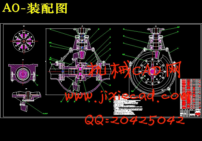
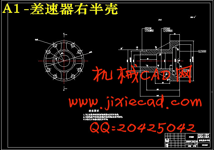
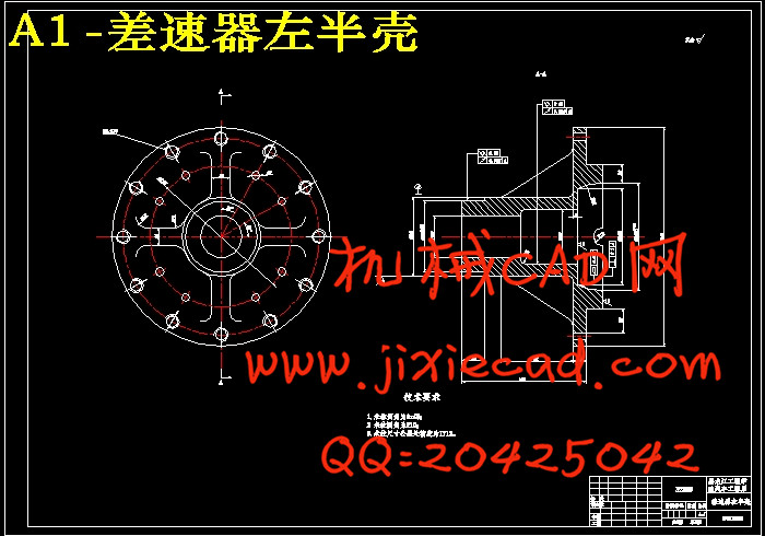
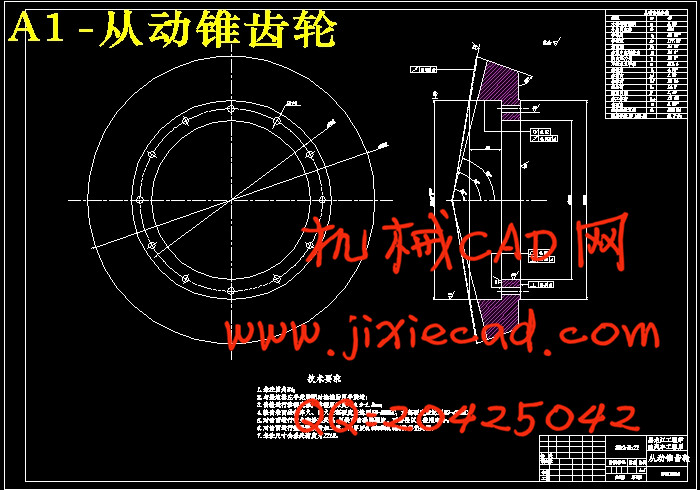
作为汽车关键零部件之一的车桥系统也得到相应的发展,在一般的汽车结构中,驱动桥包括主减速器(又称主传动器)、差速器、半轴及桥壳等部件。单级主减速器通常由主动齿轮和从动齿轮组成。在双级主减速器中,通常还要加一对圆柱齿轮或一组行星齿轮。在轮边减速器中则常采用普通平行轴式布置的斜齿圆柱齿轮传动或行星齿轮传动。主减速器采用的最广泛的是螺旋锥齿轮和双曲面齿轮。本设计首先参考类似驱动桥主减速器的结构对比优缺点,确定出总体设计方案;然后确定主要部件的结构型式和主要设计参数;最后对主,从动锥齿轮,差速器圆锥行星齿轮,半轴齿轮,全浮式半轴进行校核以及对支承轴承进行了寿命校核。并对主减速器主动锥齿轮进行有限元分析。本设计采用传统的双曲面锥齿轮式单级主减速器作为CA1090的主减速器。
关键词: CA1090;主减速器;双曲面锥齿轮;轴承;行星齿轮;有限元分析
Abstract
One of the key components of a vehicle bridge system has also been a corresponding development of the automobile in the general structure, including the main gear axle (also known as the main drive device), differential, axle and axle housing and other components. Usually single-stage final drive gear and driven gear components. In the two-stage final drive, usually also add a pair of spur gear or a group of planetary gears. Reducer in the wheel is usually arranged by common parallel shaft helical gears or planetary gears. Final drive is the most widely used spiral bevel gear and hypoid gear.The drive axle design similar to the first reference to the structure of comparative advantages and disadvantages of the main gear, determined the overall design scheme; and then identify the main components of the structure type and the main design parameters; Finally, the driving and driven bevel gear, planetary gear differential cone, axle gear, full floating axle bearings were checked and were on life support check. Bevel gear final drive and initiative to the finite element method. This design uses a traditional-style hypoid bevel final drive as the CA1090 single-stage main gear.
Key word: CA1090; Main Gear; Hypoid Gears; Bearing; Planetary Gear;FEA
目 录
摘要 ⅠAbstract Ⅱ
第1章 绪论 1
1.1 选题的目的和意义 1
1.2 国内外研究现状 1
1.3 本次设计的主要内容 3
第2章 主减速器的设计 4
2.1 结构型式的选择 4
2.1.1 减速型式 4
2.1.2 齿轮的类型的选择 4
2.1.3 主动锥齿轮的支承形式 7
2.1.4 从动锥齿轮的支承形式及安置方法 8
2.2 基本参数选择与设计计算 9
2.2.1 计算载荷的确定 9
2.2.2 基本参数的选择 11
2.2.3 双曲面齿轮的几何尺寸计算 15
2.2.4 双曲面齿轮的强度计算 23
2.2.5 齿轮的材料及热处理 28
2.3 轴承的选择 28
2.3.1 计算转矩的确定 28
2.3.2 齿宽中点处的圆周力 29
2.3.3 双曲面齿轮所受的轴向力和径向力 30
2.3.4 轴承载荷的计算及轴承的选择 31
2.4 本章小结 34
第3章 差速器设计 35
3.1 差速器结构形式的选择 35
3.2 对称式圆锥行星齿轮差速器的差速原理 36
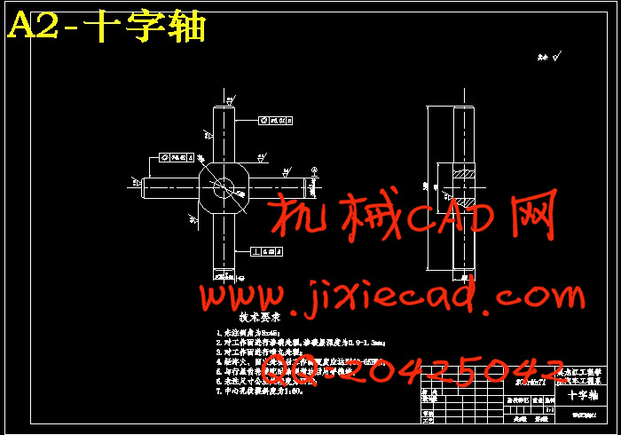
3.3 对称式圆锥行星齿轮差速器的结构 37
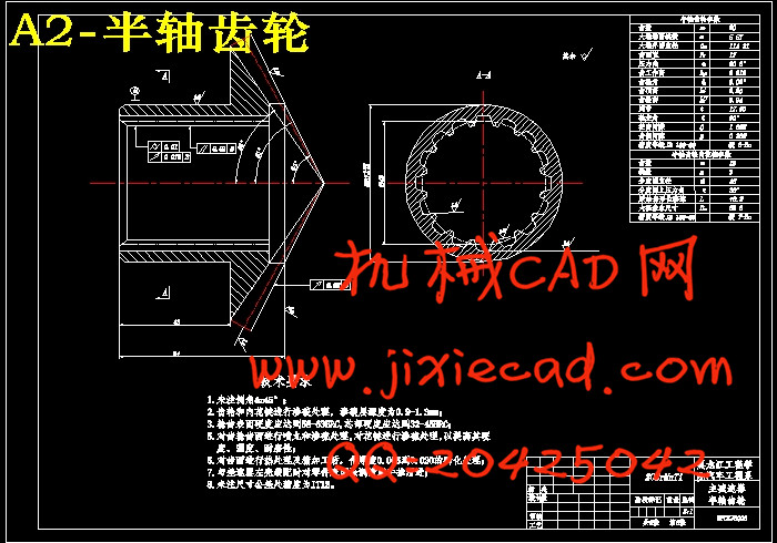
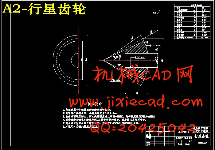
3.4 对称式圆锥行星齿轮差速器的设计 38
3.4.1 差速器齿轮的基本参数的选择 38
3.4.2 差速器齿轮的几何计算 40
3.4.3 差速器齿轮的强度计算 41
3.5 本章小结 42
第4章 驱动半轴的设计 43
4.1 半轴结构形式的选择 43
4.2 全浮式半轴计算载荷的确定 44
4.3 全浮式半轴的杆部直径的初选 45
4.4 全浮式半轴的强度计算 45
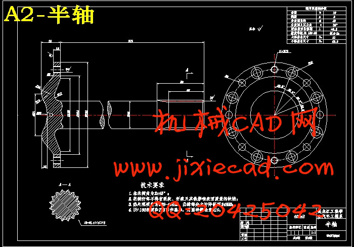
4.5 半轴花键的计算 45
4.5.1 花键尺寸参数的计算 45
4.5.2 花键的校核 48
4.6 本章小结 49
第5章 主动锥齿轮的有限元分析 50
5.1 有限元方法与ANSYS简介 50
5.2 主动锥齿轮的有限元分析 50
5.2.1 有限元模型的生成 50
5.2.2 划分网格 51
5.2.3 齿轮静载和约束的施加与结果分析 52
5.3 本章小结 54
结论 55
参考文献 56
致谢 57


