设计简介
螺旋弹簧疲劳试验机设计
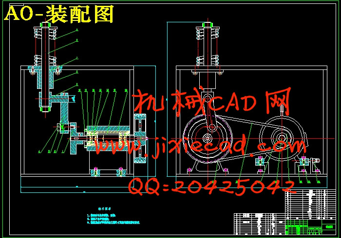
摘 要:整机结构主要由电动机、机架、传动带、偏心轮构成。由电动机产生动力通过带轮减速器将需要的动力传递到带轮上,带轮带动V带,从而带动整机装置运动
本论文研究内容摘要:
(1) 螺旋弹簧疲劳试验机总体结构设计。
(2) 螺旋弹簧疲劳试验机工作性能分析。
(3)电动机的选择。
(4)对螺旋弹簧疲劳试验机的传动系统、执行部件及机架设计。
(5)对设计零件进行设计计算分析和校核。
(6)绘制整机装配图及重要部件装配图和设计零件的零件图。
关键词:螺旋弹簧疲劳试验机,结构设计
The design of the spiral spring fatigue testing machine
摘 要:整机结构主要由电动机、机架、传动带、偏心轮构成。由电动机产生动力通过带轮减速器将需要的动力传递到带轮上,带轮带动V带,从而带动整机装置运动
本论文研究内容摘要:
(1) 螺旋弹簧疲劳试验机总体结构设计。
(2) 螺旋弹簧疲劳试验机工作性能分析。
(3)电动机的选择。
(4)对螺旋弹簧疲劳试验机的传动系统、执行部件及机架设计。
(5)对设计零件进行设计计算分析和校核。
(6)绘制整机装配图及重要部件装配图和设计零件的零件图。
关键词:螺旋弹簧疲劳试验机,结构设计
The design of the spiral spring fatigue testing machine
Abstract:The structure is mainly composed of a motor, a frame, a transmission belt, an eccentric wheel. Produced by the motor power through a belt wheel speed reducer will need to transfer the power to the belt wheel, belt wheel drives the V belt, so as to drive the movement of the whole device
Abstract this thesis research:
(1) the overall structure design of helical spring fatigue testing machine.
(2) analysis of helical spring fatigue testing machine performance.
(3) the choice of motor.
(4) transmission system, execution unit and frame design of helical spring fatigue testing machine.
(5) the design of parts of design calculation and check.
(6) drawing machine assembly drawing and assembly drawing design of important parts and parts drawings.
Keywords: helical spring fatigue testing machine, structure design
目 录
第1章 绪论 1Abstract this thesis research:
(1) the overall structure design of helical spring fatigue testing machine.
(2) analysis of helical spring fatigue testing machine performance.
(3) the choice of motor.
(4) transmission system, execution unit and frame design of helical spring fatigue testing machine.
(5) the design of parts of design calculation and check.
(6) drawing machine assembly drawing and assembly drawing design of important parts and parts drawings.
Keywords: helical spring fatigue testing machine, structure design
目 录
1.1课题研究的目的和意义 1
1.2研究内容 2
1.3设计方案 2
第2章 螺旋弹簧疲劳试验机总体参数的设计 6
2.1 系统总体方案的分析 6
2.2传动原理图 6
2.3大弹簧设计计算 7
2.4计算切削功率所需切削速度的确定 12
2.5 由切削功率推算许用工作转速 17
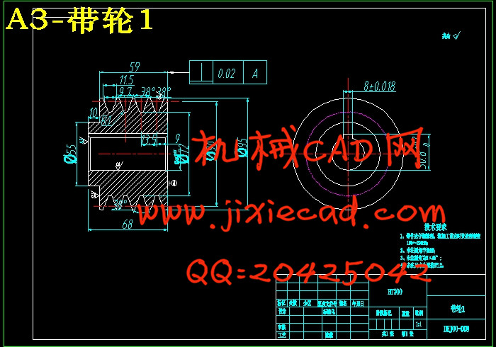
第3章 带传动的计算 20
3.1 带传动设计 20
3.2选择带型 21
3.3确定带轮的基准直径并验证带速 22
3.4确定中心距离、带的基准长度并验算小轮包角 23
3.5确定带的根数z 24
3.6确定带轮的结构和尺寸 24
3.7确定带的张紧装置 24
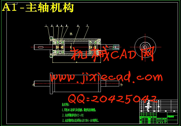
第4章 主轴组件要求与设计计算 27
4.1 主轴的基本要求 27
4.1.1 旋转精度 27
4.1.2 刚度 27
4.1.3 抗振性 28
4.1.4 温升和热变形 28
4.1.5 耐磨性 29
4.2 主轴组件的布局 29
4.3 主轴结构的初步拟定 32
4.4 主轴的材料与热处理 32
4.5 主轴的技术要求 33
4.6 主轴直径的选择 33
4.7 主轴前后轴承的选择 34
4.8 轴承的选型及校核 35
4.9 主轴前端悬伸量 37
4.10 主轴支承跨距 38
4.11 主轴结构图 39
4.12 主轴组件的验算 39
4.12.1 支承的简化 39
4.12.2 主轴的挠度 40
4.12.3 主轴倾角 41
第5章 键的选择与校核 49
5.1 带轮1上键的选择与校核 49
5.1.1键的选择 49
5.1.2 键的校核 49
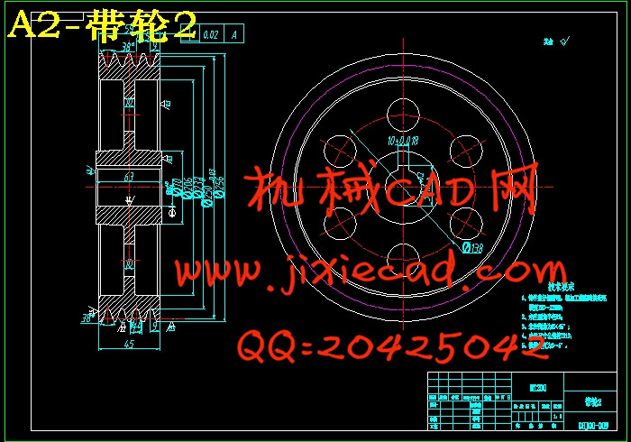
5.2 带轮2上键的选择与校核 51
5.2.1 键的选择 51
5.2.2 键的校核 51
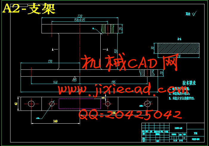
第6章 试验机其他主要零件的设计与校核 53
6.1 偏心轮尺寸的设计与校核 53
6.1.1 偏心轮尺寸的设计 53
6.1.2 偏心轮的校核 53
6.2 连接轴(一)的设计与校核 55
6.2.1 连接轴的设计 55
6.2.2 连接轴的校核 55
6.3 连接轴(二)的设计与校核 60
6.4 连杆的设计与校核 61
6.4.1 连杆的设计 61
6.4.2 连杆的校核 61
结 论 63
参考文献 64
致 谢 65