
设计简介
摘 要
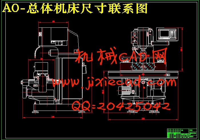
从研究铣床着手,借鉴国内外先进经验,设计了一台用于多种工件加工的铣床数控化改造,满足了生产和设计的要求。整个铣床主要包括横纵向进给机构、垂直进给机构、立柱、横梁、底座、工作台等主要组部件。其中所有进给机构均采用滚珠丝杠进行传动,并由伺服电机进行驱动。主轴箱安装在门架上,运用类比法自行设计了滚珠丝杠螺母副的制动装置。全面阐述了数控铣床的结构原理,设计特点,论述了采用伺服电机和滚珠丝杠螺母副的优点。详细介绍了数控铣床的结构设计及校核,并进行了分析。另外汇总了有关技术参数。
其中着重介绍了滚珠丝杠的原理及选用原则,系统地对滚珠丝杠生产、应用等环节进行了介绍。包括种类选择、参数选择、精度选择、循环方式选择、与主机匹配的原则以及厂家的选择等。
关键词:铣床,数控,伺服电机,滚珠丝杠
Abstract
Begins from the research CNC planer type milling machine, to profit from the domestic and foreign advanced experiences, designed one to use in the sheet material and various workpiece the numerical control CNC planer type milling machine, has satisfied the production and the design request.Elaborated comprehensively the numerical control CNC planer type milling machine's structure principle, the design feature, elaborated has used step-by-steps the electrical machinery and the ball bearing guide screw nut vice-merit. Introduced in detail the numerical control CNC planer type milling machine's structural design and the examination, and have carried on the analysis. And has compiled the related technical parameter.
In which introduced emphatically the ball bearing guide screw principle and selects the principle,To ball bearing links and so on guide screw production, application has systematically carried on the introduction. Including the type choice, the parameter choice, the precision choice, the round-robin mode choice, the principle as well as the factory choice which matches with the main engine and so on.
Key Words: milling machine, Numerical control, Step-by-step, serve motor, Ball bearing guide screw nut
目 录
Abstract III
目 录 1
第1章 数控机床发展概述 4
1.1 数控机床及其特点 4
1.1.1 数控机床与普通机床的区别 4
1.1.2 数控机床的适用范围 5
1.2 数控机床的工艺范围及加工精度 5
1.3数控机床的经济分析 6
1.3.1控制系统的选择 7
1.3.2 选择设计对象要适宜 8
1.3.3 机床的机械设计范围要适当 8
1.3.4 辅助设计要合适 9
1.4 数控机床发展趋势 9
第2章 数控机床总体方案的制订及比较 11
2.1总体方案设计的内容 11
2.1.1系统运动方式的确定 11
2.1.2伺服系统的选择 12
2.1.3执行机构传动方式的确定 12
2.1.4计算机的选择 12
2.2总体设计方案的确定 13
2.2.1系统的运动方式与伺服系统的选择 13
2.2.2计算机系统 13
2.2.3机械传动方式 13
第3章 确定切削用量及选择刀具 14
3.1刀具选择 14
3.2切削用量确定 14
3.3切削三要素 14
3.4加工精度和表面粗糙度 15
3.5刀具材料 18
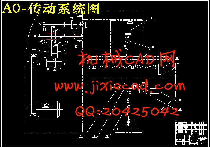
第4章 传动系统图的设计计算 19
4.1 传动系统设计 19
4.1.1 参数的拟定 19
4.1.2 传动结构或结构网的选择 19
4.1.3 转速图拟定 21
4.1.4 齿轮齿数的确定及传动系统图的绘制 24
4.2 展开图设计 27
4.2.1 结构实际的内容及技术要求 27
4.2.2 齿轮块的设计 28
4.2.3 传动轴设计 31
4.3 截面图设计 34
4.3.1 轴的空间布置 34
4.3.2 润滑 34
4.3.3 箱体设计的有关问题 35
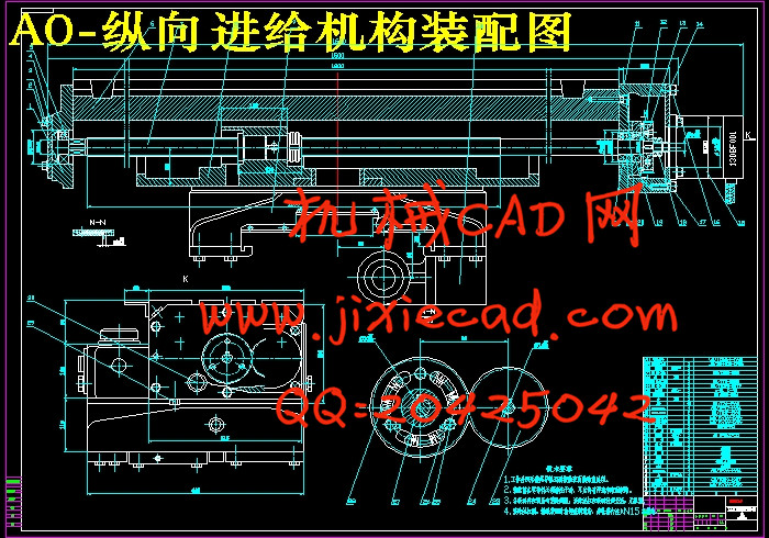
第5章 纵向进给机构的装配图和零件图设计与计算 36
5.1已知参数条件 36
5.2滚珠丝杆副主要参数的确定 36
5.3设计步骤 37
5.4设计计算 37
5.5滚珠丝杠选择 39
5.5.1滚珠丝杠精度 39
5.5.2滚珠丝杠选择 39
5.6滚珠丝杠支承选择 40
5.7滚珠丝杠螺母副间隙消除和预紧 43
5.8选择伺服电机 44
5.8.1最大的切削负载转矩计算 44
5.8.2负载惯量计算 45
5.8.3空载加速转矩计算 46
5.9伺服系统增益 47
5.10精度验算 48
5.10.1伺服刚度 48
5.10.2滚珠丝杠的拉压刚度 49
5.10.3丝杠轴承的轴向刚度 49
5.10.4滚珠丝杠螺母的接触刚度 49
5.10.5挠性联轴节扭转刚度 50
5.10.6综合刚度 50
5.10.7弹性变形 50
5.10.8定位误差验算 50
总结 52
参考文献 53
致谢 54