
设计简介
摘要
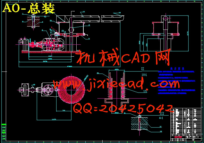
船用废气燃烧臂是一种用于排放轮船尾气的一套装备,其中燃烧臂为悬臂结构.在现有的燃烧臂过程中,一般采用船用吊机的设计方法所设计的结构过于保守,使得结构质量偏大.燃烧臂结构安全系数会过大,不仅导致材料浪费和成本增加,而且还会对整个船体的稳定性不利.回面燃烧臂结构需要进行专门的设计.本文燃烧臂底座采用了专门用于回转的回转支承.
回转支承装置是近30年来发展起来的新型机器部件,它已从用子挖掘机和起重仇逐渐发展到用于其它机械。 回转支承装置近乎特大型的滚动轴承。它将机器的上部和下部连接起来,用以支承上部的重量和工作负荷,并使上部能相对于下部旋转。本文对燃烧臂底座进行了弯曲强度,剪切强度及抗挤压强度的校核.
而其燃烧臂上部桁架机构的设计比一般船用吊机要轻巧得多,对此燃烧臂结构需要进行单独的强度计算.
由于所要设计的燃烧臂回转速度仅为1/6(r/min),因此,为了考虑其使用效率只使用一个圆锥-圆柱减速度器,故,在此次设计中选用了直接带减速装置的凸缘安装型式电动机,此电动机不仅功率和输出转矩能满足要求,而且其输出转速仅为25n/min.
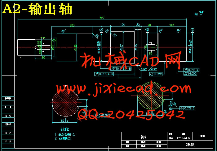
在回转速度低,功率大的燃烧臂装置中,所要求的减速器轴需要很高的强度,因此通过参考一些比较权威的机械设计手册之后,再通过强度校核,选用减速器的轴材料为20CrMn.
关键词:回转支承,圆锥-圆柱减速度器,
Abstract
Marine from a burning arm for the tail gas emissions set of vessels and equipment, including combustion for the cantilever arm structure. Arm of the existing combustion process, the general marine crane designed by the design of the structure was too conservative, making the quality of the structure Too large. Combustion arm structural safety factor would be too large, not only lead to waste and material cost increases, but also the stability of the entire hull negative. Back-burner arm of the need for specialized design. Combustion arm base paper used a special use Rotary in the rotary bearing.
Rotary support device is nearly 30 years ago to develop a new type of machine components, it has been used excavator and the lifting of hatred to the progressive development of other machinery for. Rotary supporting device near the large rolling bearings. The machine will link the upper and lower to the upper bearing the weight and work load, and the upper to the lower part of the rotation. In this paper, the base of a burning arm bending strength, shear strength and the strength of anti-extrusion check. Combustion arm of the Department and its agencies truss design than the general marine hanging confidential lightweight much, this burning need for a separate arm of the Strength calculation.
Because the design of the combustion rotary arm speed is only 1 / 6 (r / min), therefore, in order to consider only the use of its efficiency in the use of a cone - cylindrical cut speed, so that in this design selected directly with the slowdown in device Flange installation type motor, the motor not only power and torque output to meet demand, but its output speed is only 25 n / min.
Rotary in the low-speed, large power plant burning arm, the required reducer axis need a high intensity, some of the more authoritative reference by the mechanical design manual, to check through strength, the choice of reducer shaft material for 20 CrMn .
Key words: slewing bearings, cone - cylindrical cut speed,
目录
1.燃烧臂机构的设计---------------------------------- (1)
1.1 燃烧臂装置的方案设计-------------------------------------(1)
1.2 燃烧臂的选型计算-----------------------------------------(1)
1.2.1燃烧臂的基本结构-------------------------------------(1)
1.2.2水平支架的方案设计-----------------------------------(1)
1.2.3 水平支架的受力分析-----------------------------------(2)
1.2.4 水平支架的强度计算-----------------------------------(3)
1.3 垂直支架的方案设计--------------------------------------(4)
2.回转机构的设计------------------------------------ (6)
2.1概述----------------------------------------------------(6)
2.1.1 回转支承的型式与结构------------------------------(13)
2.2 根据所知条件设立回转方案-------------------------------(12)
2.3船用废气燃烧臂的负荷分析---------------------------------(14)
2.3.1 船用废气燃烧臂的外力分析--------------------------(14)
2.3.2 回转摩擦阻力矩的计算-------------------------------(14)
2.3.3 与回转支承相配合的小齿轮的尺寸几何计算-------------(15)
3.船用废气燃烧臂减速器的设计---------------------- -(16)
3.1 电动机的选择---------------------------------(16)
3.1.1 选择电动机类型----------------------------------(16)
3.1.2选择电动机容量----------------------------------(17)
3.1.3传动装置的总传动比及其分配----------------------(18)
3.1.4 计算传动装置的运动和动力参数--------------------(18)
3.2 传动方案设计
3.2.1 确定传动类型---------------------------------- (19)
3.2.2 总传动比和合理分配各级传动比-------------------(20)
3.3齿轮传动的设计与校核-------------------------(21)
3.3.1 轮齿的失效形式--------------------------------(22)
3.3.2变位齿轮简介----------------------------------(23)
3.3.3 齿轮设计准则---------------------------------(25)
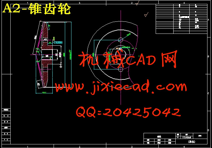
3.3.4 高-切变位弧齿锥齿轮传动主要尺寸的确定--------(25)
3.3.5高-切变位弧齿锥齿轮正交传动的几何计算---------(27)
3.3.6 高-切变位弧齿锥齿轮接触强度校核-------------(29)
3.4高变位斜齿轮传动主要尺寸的确定-------------(32)
3.4.1高变位齿轮齿轮主要尺寸的初步确定-------------(33)
3.4.2高变位斜齿轮外啮合传动的几何计算------------(34)
3.4.3高变位斜齿轮接触强度校核--------------------(35)
3.5齿轮结构形式的确定------------------------(36)
3.5.1高-切变位弧齿锥齿轮结构形式-----------------(36)
3.5.2高变位斜齿轮结构形式-------------------------(37)
3.6传动轴的结构设计与校核--------------------(37)
3.6.1.输入轴的设计-------------------------------(38)
3.6.1.1确定轴的最小直径-------------------(38)
3.6.1.2 按轴向定位要求确定各轴段直径和长度---
--------------------------(39)
3.6.1.3 轴上零件的轴向定位及轴上圆角和倒角的尺寸------------------------(40)
3.6.2中间轴的结构设计--------------------------(40)
3.6.2.1 确定轴的最小直径------------------(40)
3.6.2.2按轴向定位要求确定各轴段直径和长度---
-------------------------(41)
3.6.2.3轴上零件的轴向定位及轴上圆角和倒角的尺寸------------------------(41)
3.6.3输出轴的结构设计 -------------------(42)
3.6.3.1 确定轴的最小直径----------------(42)
3.6.3.2按定位要求确定各轴段直径和长度------
--------------------- (42)
3.7传动轴的弯扭合成强度计算与疲劳强度校核------
-------------------(44)
3.7.1传动轴的受力分析--------------------------(44)
3.7.2轴的弯扭合成强度校核----------------------(54)
3.7.3精确校核轴的疲劳强度----------------------(51)
3.8轴承与键的校核-------------------------(53)
3.8.1单列圆锥滚子轴承的寿命校核--------------(53)
3.8.2A型平键的强度校核-----------------------(54)
3.9 轴系部件的结构设计------------------------(55)
3.9.1 轴承盖的结构设计-----------------------(55)
3.10箱体及附件的设计---------------------(57)
3.11 减速器箱体的设计---------------------(57)
3.11.1 油面位置及箱座高度的确定-------------(59)
3.11.2 油沟的结构形式及尺寸-----------------(59)
3.12减速器的附件-------------------------(60)
3.12.1 检查孔与检查孔盖的设计---------------(60)
3.12.2 通气器的结构及尺寸-------------------(61)
3.12.3 放油孔、螺塞和封油圈-----------------(61)
3.12.4 油标指示器----------------------------(62)
3.12.5 起吊装置------------------------------(63)
3.12.6 定位销---------------------------------(64)
3.12.6 定位销---------------------------------(65)
3.13减速器主要零件的加工工艺---------------(65)
3.13.1 零件图样分析---------------------------(66)
3.13.2 中间轴的机械加工工艺过程卡-------------(66)
4.船用废气燃烧臂其它部件的设计------------------(67)
4.1 排气管的选择-----------------------------------(67)
4.2 O形橡胶密封圈----------------------------------(67)
参考文献—————————————————-----(69)
英文翻译————————————————————————(70)
结论 ------------------------------------------(78)
致谢-------------------------------------------(79)
船用废气燃烧臂是一种用于排放轮船尾气的一套装备,其中燃烧臂为悬臂结构.在现有的燃烧臂过程中,一般采用船用吊机的设计方法所设计的结构过于保守,使得结构质量偏大.燃烧臂结构安全系数会过大,不仅导致材料浪费和成本增加,而且还会对整个船体的稳定性不利.回面燃烧臂结构需要进行专门的设计.本文燃烧臂底座采用了专门用于回转的回转支承.
回转支承装置是近30年来发展起来的新型机器部件,它已从用子挖掘机和起重仇逐渐发展到用于其它机械。 回转支承装置近乎特大型的滚动轴承。它将机器的上部和下部连接起来,用以支承上部的重量和工作负荷,并使上部能相对于下部旋转。本文对燃烧臂底座进行了弯曲强度,剪切强度及抗挤压强度的校核.
而其燃烧臂上部桁架机构的设计比一般船用吊机要轻巧得多,对此燃烧臂结构需要进行单独的强度计算.
由于所要设计的燃烧臂回转速度仅为1/6(r/min),因此,为了考虑其使用效率只使用一个圆锥-圆柱减速度器,故,在此次设计中选用了直接带减速装置的凸缘安装型式电动机,此电动机不仅功率和输出转矩能满足要求,而且其输出转速仅为25n/min.
在回转速度低,功率大的燃烧臂装置中,所要求的减速器轴需要很高的强度,因此通过参考一些比较权威的机械设计手册之后,再通过强度校核,选用减速器的轴材料为20CrMn.
关键词:回转支承,圆锥-圆柱减速度器,
Abstract
Marine from a burning arm for the tail gas emissions set of vessels and equipment, including combustion for the cantilever arm structure. Arm of the existing combustion process, the general marine crane designed by the design of the structure was too conservative, making the quality of the structure Too large. Combustion arm structural safety factor would be too large, not only lead to waste and material cost increases, but also the stability of the entire hull negative. Back-burner arm of the need for specialized design. Combustion arm base paper used a special use Rotary in the rotary bearing.
Rotary support device is nearly 30 years ago to develop a new type of machine components, it has been used excavator and the lifting of hatred to the progressive development of other machinery for. Rotary supporting device near the large rolling bearings. The machine will link the upper and lower to the upper bearing the weight and work load, and the upper to the lower part of the rotation. In this paper, the base of a burning arm bending strength, shear strength and the strength of anti-extrusion check. Combustion arm of the Department and its agencies truss design than the general marine hanging confidential lightweight much, this burning need for a separate arm of the Strength calculation.
Because the design of the combustion rotary arm speed is only 1 / 6 (r / min), therefore, in order to consider only the use of its efficiency in the use of a cone - cylindrical cut speed, so that in this design selected directly with the slowdown in device Flange installation type motor, the motor not only power and torque output to meet demand, but its output speed is only 25 n / min.
Rotary in the low-speed, large power plant burning arm, the required reducer axis need a high intensity, some of the more authoritative reference by the mechanical design manual, to check through strength, the choice of reducer shaft material for 20 CrMn .
Key words: slewing bearings, cone - cylindrical cut speed,
目录
1.燃烧臂机构的设计---------------------------------- (1)
1.1 燃烧臂装置的方案设计-------------------------------------(1)
1.2 燃烧臂的选型计算-----------------------------------------(1)
1.2.1燃烧臂的基本结构-------------------------------------(1)
1.2.2水平支架的方案设计-----------------------------------(1)
1.2.3 水平支架的受力分析-----------------------------------(2)
1.2.4 水平支架的强度计算-----------------------------------(3)
1.3 垂直支架的方案设计--------------------------------------(4)
2.回转机构的设计------------------------------------ (6)
2.1概述----------------------------------------------------(6)
2.1.1 回转支承的型式与结构------------------------------(13)
2.2 根据所知条件设立回转方案-------------------------------(12)
2.3船用废气燃烧臂的负荷分析---------------------------------(14)
2.3.1 船用废气燃烧臂的外力分析--------------------------(14)
2.3.2 回转摩擦阻力矩的计算-------------------------------(14)
2.3.3 与回转支承相配合的小齿轮的尺寸几何计算-------------(15)
3.船用废气燃烧臂减速器的设计---------------------- -(16)
3.1 电动机的选择---------------------------------(16)
3.1.1 选择电动机类型----------------------------------(16)
3.1.2选择电动机容量----------------------------------(17)
3.1.3传动装置的总传动比及其分配----------------------(18)
3.1.4 计算传动装置的运动和动力参数--------------------(18)
3.2 传动方案设计
3.2.1 确定传动类型---------------------------------- (19)
3.2.2 总传动比和合理分配各级传动比-------------------(20)
3.3齿轮传动的设计与校核-------------------------(21)
3.3.1 轮齿的失效形式--------------------------------(22)
3.3.2变位齿轮简介----------------------------------(23)
3.3.3 齿轮设计准则---------------------------------(25)
3.3.4 高-切变位弧齿锥齿轮传动主要尺寸的确定--------(25)
3.3.5高-切变位弧齿锥齿轮正交传动的几何计算---------(27)
3.3.6 高-切变位弧齿锥齿轮接触强度校核-------------(29)
3.4高变位斜齿轮传动主要尺寸的确定-------------(32)
3.4.1高变位齿轮齿轮主要尺寸的初步确定-------------(33)
3.4.2高变位斜齿轮外啮合传动的几何计算------------(34)
3.4.3高变位斜齿轮接触强度校核--------------------(35)
3.5齿轮结构形式的确定------------------------(36)
3.5.1高-切变位弧齿锥齿轮结构形式-----------------(36)
3.5.2高变位斜齿轮结构形式-------------------------(37)
3.6传动轴的结构设计与校核--------------------(37)
3.6.1.输入轴的设计-------------------------------(38)
3.6.1.1确定轴的最小直径-------------------(38)
3.6.1.2 按轴向定位要求确定各轴段直径和长度---
--------------------------(39)
3.6.1.3 轴上零件的轴向定位及轴上圆角和倒角的尺寸------------------------(40)
3.6.2中间轴的结构设计--------------------------(40)
3.6.2.1 确定轴的最小直径------------------(40)
3.6.2.2按轴向定位要求确定各轴段直径和长度---
-------------------------(41)
3.6.2.3轴上零件的轴向定位及轴上圆角和倒角的尺寸------------------------(41)
3.6.3输出轴的结构设计 -------------------(42)
3.6.3.1 确定轴的最小直径----------------(42)
3.6.3.2按定位要求确定各轴段直径和长度------
--------------------- (42)
3.7传动轴的弯扭合成强度计算与疲劳强度校核------
-------------------(44)
3.7.1传动轴的受力分析--------------------------(44)
3.7.2轴的弯扭合成强度校核----------------------(54)
3.7.3精确校核轴的疲劳强度----------------------(51)
3.8轴承与键的校核-------------------------(53)
3.8.1单列圆锥滚子轴承的寿命校核--------------(53)
3.8.2A型平键的强度校核-----------------------(54)
3.9 轴系部件的结构设计------------------------(55)
3.9.1 轴承盖的结构设计-----------------------(55)
3.10箱体及附件的设计---------------------(57)
3.11 减速器箱体的设计---------------------(57)
3.11.1 油面位置及箱座高度的确定-------------(59)
3.11.2 油沟的结构形式及尺寸-----------------(59)
3.12减速器的附件-------------------------(60)
3.12.1 检查孔与检查孔盖的设计---------------(60)
3.12.2 通气器的结构及尺寸-------------------(61)
3.12.3 放油孔、螺塞和封油圈-----------------(61)
3.12.4 油标指示器----------------------------(62)
3.12.5 起吊装置------------------------------(63)
3.12.6 定位销---------------------------------(64)
3.12.6 定位销---------------------------------(65)
3.13减速器主要零件的加工工艺---------------(65)
3.13.1 零件图样分析---------------------------(66)
3.13.2 中间轴的机械加工工艺过程卡-------------(66)
4.船用废气燃烧臂其它部件的设计------------------(67)
4.1 排气管的选择-----------------------------------(67)
4.2 O形橡胶密封圈----------------------------------(67)
参考文献—————————————————-----(69)
英文翻译————————————————————————(70)
结论 ------------------------------------------(78)
致谢-------------------------------------------(79)