
设计简介
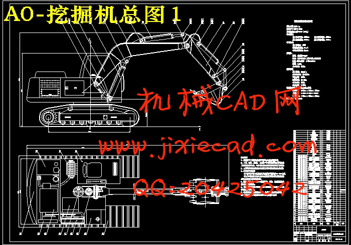
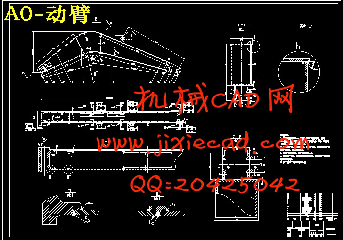
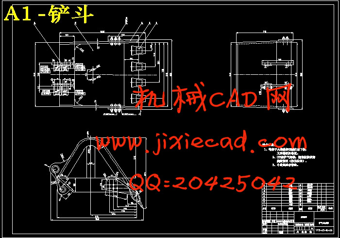
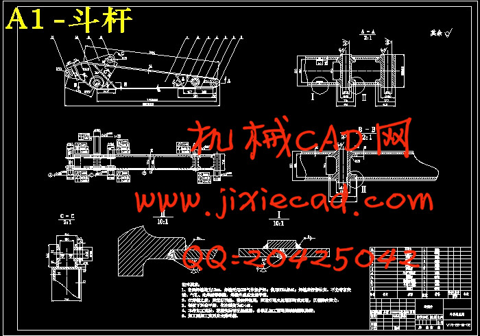
摘要:工作装置是液压挖掘机的主要组成部分之一。因用途不同,工作装置的种类繁多,其中最主要的有反铲装置、正铲装置、起重装置等。液压挖掘机工作装置主要由动臂、动臂油缸、斗杆、斗杆油缸、铲斗、铲斗油缸、摆动杆和连杆组成。对工作装置的性能分析及参数设计主要包括各铰点位置的几何尺寸、各油缸的几何尺寸、运动参数、各构件的质量和质量中心坐标、转动惯量、各油缸的工作压力和闭锁压力等。这些参数对挖掘机的工作范围、挖掘力的大小和分布、作业循环时间和功率利用等工作性能有很大的影响。
本书从设计的角度,以单斗液压挖掘机反铲工作装置为例,对动臂、斗杆、铲斗的结构及运动做了详尽的分析,对挖掘力、油缸的闭锁压力及几何尺寸均做了详细的论述。
关键词: 挖掘机;反铲装置;挖掘力;动臂机构;铲斗机构
Abstract:The working device is one of the main components of the hydraulic excavator. Because uses are different, working device are various in styles, among them having against the device of the shovel, lifting the device, jack-up device etc. mainly. The hydraulic excavator working device is mainly moved the arm, moved the arm cylinder, struggled against the pole, struggled against cylinder of the pole, scraper bowl, scraper bowl cylinder, swung the pole and connecting rod to make up. Design and include the geometirc size of every hinge point position to analysis of performance and parameter of the working device , every cylinder of geometirc size, movement parameter, every component of quality and mass centre coordinate, rotate inertia, every cylinder of working pressures and lock pressure,etc.ses. Working performance has very great influence on these parameters are utilized to the working range, size, distribution, homework circulation time and power which excavate strength of the excavator,etc..
This book regards struggling against the hydraulic excavator the example against the job device of the shovel only as in term of designing, have made exhaustive analysis in moving arm, structure and movement of the pole, scraper bowl of fighting, to excavating locking the pressure and geometirc size and doing the detailed argumentation of strength, every cylinder.
Key words:excavator; counter-shovel installment; excavation strength;boom agencies; scoop organization
目 录
前言……………………………………………………………………………………… 1
一、绪论…………………………………………………………………………………2
(一)国内外研究状况………………………………………………………………2
(二)论文构成及研究内容…………………………………………………………2
二、总体方案设计……………………………………………………………………3
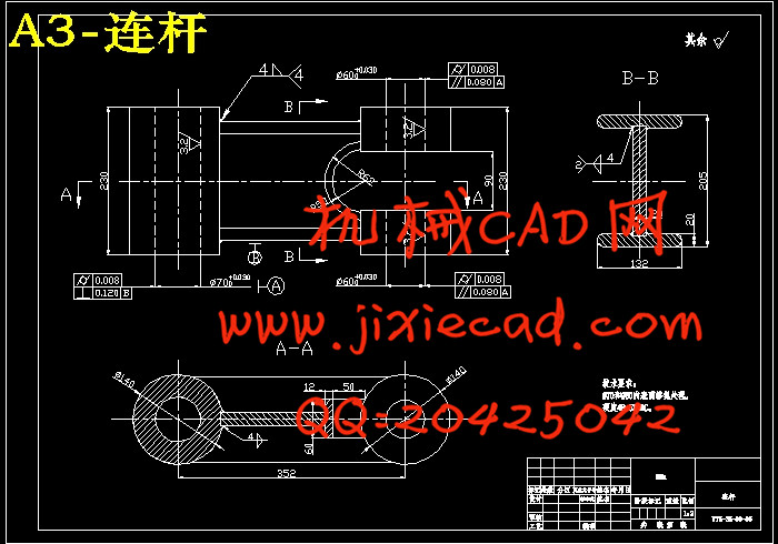
(一)工作装置构成…………………………………………………………………3
(二)动臂及斗杆的结构形式………………………………………………………5
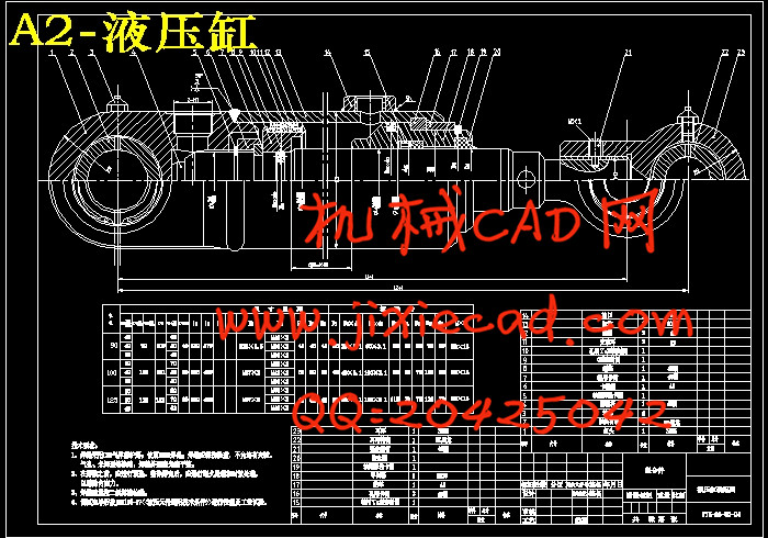
(三)动臂油缸与铲斗油缸的布置…………………………………………………5
(四)铲斗与铲斗油缸的连接方式…………………………………………………5
(五)铲斗的结构选择………………………………………………………………6
(六)原始几何参数的确定…………………………………………………………7
三、工作装置运动学分析…………………………………………………………8
(一)动臂运动分析…………………………………………………………………8
(二)斗杆的运动分析………………………………………………………………10
(三)铲斗的运动分析………………………………………………………………11
(四)特殊工作位置计算……………………………………………………………15
四、挖掘阻力分析……………………………………………………………………18
(一)转斗挖掘阻力计算……………………………………………………………18
(二)斗杆挖掘阻力计算……………………………………………………………18
五、基本尺寸的确定……………………………………………………………… 20
(一)斗形参数的确定………………………………………………………………20
(二)动臂机构参数的选择…………………………………………………………20
1、 α1与A点坐标的选取……………………………………………………20
2、 l1与l2的选择……………………………………………………………20
3、 l41与l42的计算…………………………………………………………21
4、 l5的计算………………………………………………………………… 21
(三)动臂机构基本参数的校核………………………………………………… 23
1、 动臂机构闭锁力的校核……………………………………………………23
2、 满斗处于最大挖掘半径时动臂油缸提升力矩的校核……………………25
3、 满斗处于最大高度时,动臂提升力矩的校核…………………………… 26
(四)斗杆机构基本参数的选择……………………………………………………27
(五)铲斗机构基本参数的选择……………………………………………………28
1、 转角范围……………………………………………………………………28
2、 铲斗机构其它基本参数的计算……………………………………………28
六、工作装置结构设计…………………………………………………………… 30
(一)斗杆的结构设计………………………………………………………………30
1、斗杆的受力分析…………………………………………………………… 30
2、斗杆内力图的绘制………………………………………………………… 35
3、 结构尺寸的计算……………………………………………………………37
(二)动臂结构设计…………………………………………………………………39
1、危险工况受力分析………………………………………………………… 42
2、内力图和弯矩图的求解…………………………………………………… 43
3、 结构尺寸的计算……………………………………………………………45
(三)铲斗的设计……………………………………………………………………47
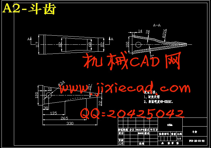
1、铲斗斗形尺寸的设计……………………………………………………… 47
2、铲斗斗齿的结构计算……………………………………………………… 47
3、 铲斗的绘制…………………………………………………………………48
七、销轴与衬套的设计…………………………………………………………… 49
(一)销轴的设计……………………………………………………………………49
(二)销轴用螺栓的设计……………………………………………………………49
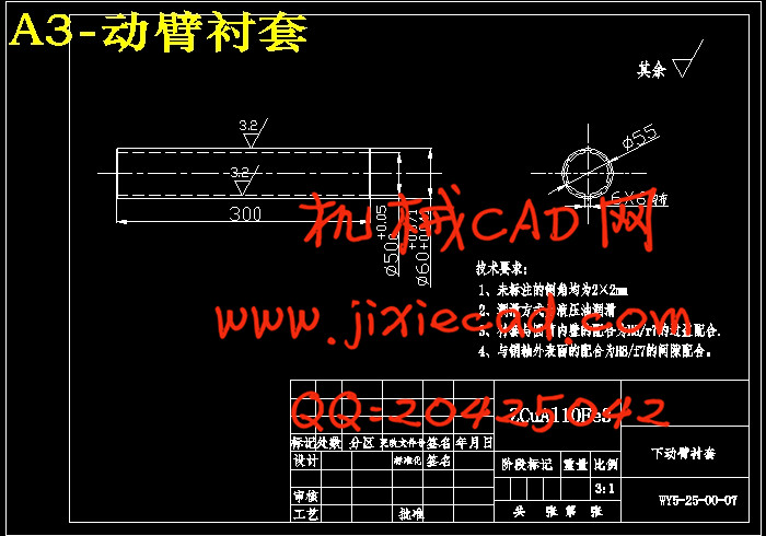
(三)衬套的设计……………………………………………………………………49
八、总结…………………………………………………………………………………50
九、参考文献………………………………………………………………………… 51
十、致谢…………………………………………………………………………………52
本书从设计的角度,以单斗液压挖掘机反铲工作装置为例,对动臂、斗杆、铲斗的结构及运动做了详尽的分析,对挖掘力、油缸的闭锁压力及几何尺寸均做了详细的论述。
关键词: 挖掘机;反铲装置;挖掘力;动臂机构;铲斗机构
Abstract:The working device is one of the main components of the hydraulic excavator. Because uses are different, working device are various in styles, among them having against the device of the shovel, lifting the device, jack-up device etc. mainly. The hydraulic excavator working device is mainly moved the arm, moved the arm cylinder, struggled against the pole, struggled against cylinder of the pole, scraper bowl, scraper bowl cylinder, swung the pole and connecting rod to make up. Design and include the geometirc size of every hinge point position to analysis of performance and parameter of the working device , every cylinder of geometirc size, movement parameter, every component of quality and mass centre coordinate, rotate inertia, every cylinder of working pressures and lock pressure,etc.ses. Working performance has very great influence on these parameters are utilized to the working range, size, distribution, homework circulation time and power which excavate strength of the excavator,etc..
This book regards struggling against the hydraulic excavator the example against the job device of the shovel only as in term of designing, have made exhaustive analysis in moving arm, structure and movement of the pole, scraper bowl of fighting, to excavating locking the pressure and geometirc size and doing the detailed argumentation of strength, every cylinder.
Key words:excavator; counter-shovel installment; excavation strength;boom agencies; scoop organization
目 录
前言……………………………………………………………………………………… 1
一、绪论…………………………………………………………………………………2
(一)国内外研究状况………………………………………………………………2
(二)论文构成及研究内容…………………………………………………………2
二、总体方案设计……………………………………………………………………3
(一)工作装置构成…………………………………………………………………3
(二)动臂及斗杆的结构形式………………………………………………………5
(三)动臂油缸与铲斗油缸的布置…………………………………………………5
(四)铲斗与铲斗油缸的连接方式…………………………………………………5
(五)铲斗的结构选择………………………………………………………………6
(六)原始几何参数的确定…………………………………………………………7
三、工作装置运动学分析…………………………………………………………8
(一)动臂运动分析…………………………………………………………………8
(二)斗杆的运动分析………………………………………………………………10
(三)铲斗的运动分析………………………………………………………………11
(四)特殊工作位置计算……………………………………………………………15
四、挖掘阻力分析……………………………………………………………………18
(一)转斗挖掘阻力计算……………………………………………………………18
(二)斗杆挖掘阻力计算……………………………………………………………18
五、基本尺寸的确定……………………………………………………………… 20
(一)斗形参数的确定………………………………………………………………20
(二)动臂机构参数的选择…………………………………………………………20
1、 α1与A点坐标的选取……………………………………………………20
2、 l1与l2的选择……………………………………………………………20
3、 l41与l42的计算…………………………………………………………21
4、 l5的计算………………………………………………………………… 21
(三)动臂机构基本参数的校核………………………………………………… 23
1、 动臂机构闭锁力的校核……………………………………………………23
2、 满斗处于最大挖掘半径时动臂油缸提升力矩的校核……………………25
3、 满斗处于最大高度时,动臂提升力矩的校核…………………………… 26
(四)斗杆机构基本参数的选择……………………………………………………27
(五)铲斗机构基本参数的选择……………………………………………………28
1、 转角范围……………………………………………………………………28
2、 铲斗机构其它基本参数的计算……………………………………………28
六、工作装置结构设计…………………………………………………………… 30
(一)斗杆的结构设计………………………………………………………………30
1、斗杆的受力分析…………………………………………………………… 30
2、斗杆内力图的绘制………………………………………………………… 35
3、 结构尺寸的计算……………………………………………………………37
(二)动臂结构设计…………………………………………………………………39
1、危险工况受力分析………………………………………………………… 42
2、内力图和弯矩图的求解…………………………………………………… 43
3、 结构尺寸的计算……………………………………………………………45
(三)铲斗的设计……………………………………………………………………47
1、铲斗斗形尺寸的设计……………………………………………………… 47
2、铲斗斗齿的结构计算……………………………………………………… 47
3、 铲斗的绘制…………………………………………………………………48
七、销轴与衬套的设计…………………………………………………………… 49
(一)销轴的设计……………………………………………………………………49
(二)销轴用螺栓的设计……………………………………………………………49
(三)衬套的设计……………………………………………………………………49
八、总结…………………………………………………………………………………50
九、参考文献………………………………………………………………………… 51
十、致谢…………………………………………………………………………………52