设计简介
摘 要
近20年来,气动技术的应用领域迅速拓宽,尤其是在各种自动化生产线上得到广泛应用。电气可编程控制技术与气动技术相结合,使整个系统自动化程度更高,控制方式更灵活,性能更加可靠;气动机械手、柔性自动生产线的迅速发展,对气动技术提出了更多更高的要求。
本课题设计源于生产线中的搬运站,传动方式采用气压传动,即用各种气缸来控制机械手的动作,控制部分结合可编程控制技术编写程序进行控制来实现两站之间的搬运。
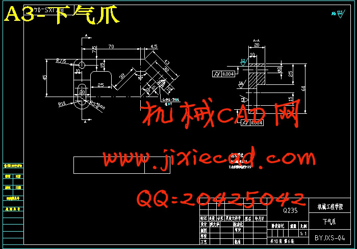
机械手主要由手部、运动机构和控制系统三大部分组成。手部是用来抓持工件(或工具)的部件,根据被抓持物件的形状、尺寸、重量、材料和作业要求而有多种结构形式,如夹持型、托持型和吸附型等。运动机构,使手部完成各种转动(摆动)、移动或复合运动来实现规定的动作,改变被抓持物件的位置和姿势。运动机构的升降、伸缩、旋转等独立运动方式,称为机械手的自由度 。本课题中设计的搬运机械手主要有旋转、伸缩、升降、夹紧四个自由度组成。
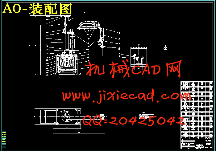
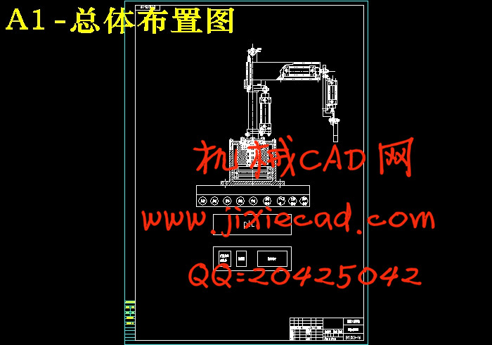
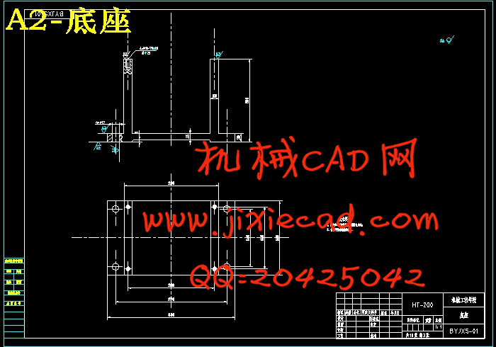
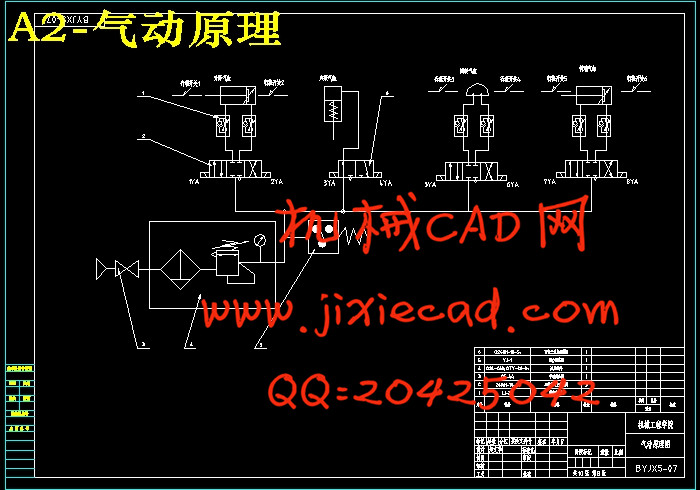
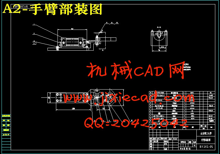
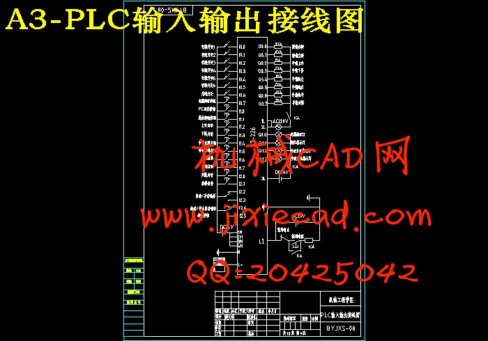
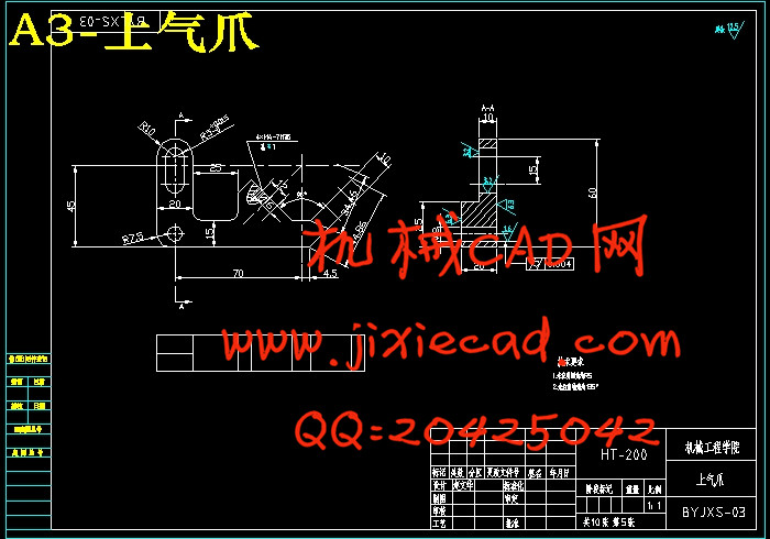
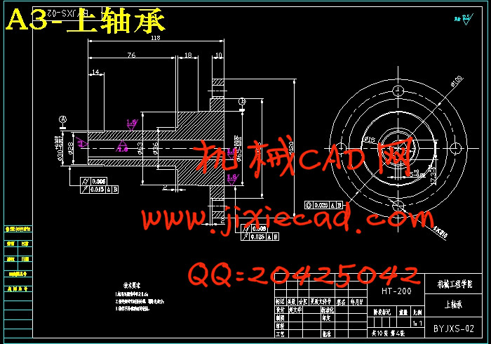
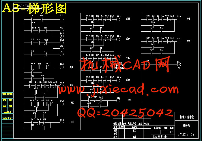
课题从机械部分、气动部分和控制三部分对气动机械手进行设计,要求机械手实现上下站之间的搬运功能。机械部分重点是总体结构的设计、各个气缸的选择和安装设计、各零部件的结构设计等,气动部分主要是给出了搬运机械手的气动原理图,而控制部分则主要是程序的设计和调试,论文采用西门子(S7-200)指令编程,给出了相应的梯形图、语句表和简单的流程图。
由于气动机械手有结构简单、易实现无级调速、易实现过载保护、易实现复杂的动作等诸多独特的优点,气动机械手正在向重复高精度,模块化,无给油化, 机电气一体化方向发展。可以预见,在不久的将来,气动机械手将越来越广泛地进人工业、军事、航空、医疗、生活等领域。
关键词:可编程控制器,柔性自动生产线,自由度,梯形图
Abstract
Over the past 20 years, the field of pneumatic technology expand rapidly,which is widely used in a diverse array of automated production line especially.The combine of electrical programmable technology and pneumatic control technology makes the whole system a higher degree of automation, more flexible control and more reliable performance;The rapid develop of pneumatic manipulator and flexible automated production lines requier much more to the development of pneumatic technology .
This topic originated from the handling station of the production line;The drive is used pressure transmission, which uses a variety of cylinder to control the robot's movement and the control parts combining the programmable control technology make a programme to achieve the control of the transportation between the two places.
Manipulator is competed by three major parts including hand, sports bodies and control system. Task of hand is to hold the workpiece (or tool) of the components.According to the grasping object’s shape, size, weight, materials and operating requirements the hand hands a variety of structural forms, such as clamp type, ADS holders and adsorption type and so on.The movement part can complete the prescriptive move and achieve the change of the site and gesture of the grasping objects by varies rotating(twisting),moving or complex movements on hand. The independence movements such as the rise and fall of body, stretching and rotating manner are called the free degrees of manipulator. The handling manipulator of the topic composites four free degrees which are rotation, stretching, lifting and claping
The pneumatic manipulator design is desided from three parts in chuding the mechanical parts, pneumatic parts and control parts,which requires to achieve mechanical hand up and down between the handling function. Focus on the mechanical parts are the design of overall structure , the choice of each cylinder and installation design, structural design of various components etc; pneumatic part is given the pneumatic manipulator handling schematics, and the control part of the procedure was mainly design and debugging,The papers use Siemens (S7-200) instructions program,giving the corresponding ladder diagram, statement forms and simple flow chart.
Because the pneumatic Manipulator has advantages of simple structure, easy to achieve the stepless speed regulation, easy to achieve overload protection, easy to achieve a number of complex movements,the pneumatic manipulator is developing to the repeat-high-precision, modular, non-oil and electrical integration direction. It is foreseeable that in the near future, pneumatic manipulator will become more and more widely used into the industrial, military, aviation, medical, and other areas of life.
Keywords:PLC, flexible automated production lines, free degree, Ladder Diagram
Abstract(英文摘要) Ⅱ
目 录 IV
第一章 引 言 1
1.1 课题的背景和意义 1
1.2 课题国内外发展现状 2
第二章 总体方案确定 4
2.1 总体方案论证 4
2.1.1 机械手手臂结构方案设计 4
2.1.2 机械手驱动方案设计 4
2.1.3 机械手控制方案设计 5
2.1.4 机械手主要参数 5
2.1.5 机械手的技术参数列表 6
第三章 机械手总体结构设计 7
3.1 动作工况与分析 7
3.2 机械手各部分结构设计 8
3.2.1 机械手底座的设计 8
3.2.2 立柱结构的设计 8
3.2.3 轴承的选择 9
3.2.4 上轴承座的选择 10
3.2.5 下轴承座的选择 11
3.2.6 大臂的结构设计 12
3.2.7 小臂的结构设计 12
3.2.8 气爪的结构设计 12
3.2.9 手部夹紧气缸设计计算 14
3.2.10 升降气缸设计计算 18
3.2.11 伸缩气缸设计计算 22
3.2.12 回转气缸设计计算 25
第四章 气动部分设计 28
第五章 PLC控制部分设计 30
5.1电磁铁动作顺序 30
5.2 I/O分配 30
5.3 PLC控制梯形图 31
5.4 PLC控制程序指令 32
结论 37
参考文献 38
致谢及声明 39
近20年来,气动技术的应用领域迅速拓宽,尤其是在各种自动化生产线上得到广泛应用。电气可编程控制技术与气动技术相结合,使整个系统自动化程度更高,控制方式更灵活,性能更加可靠;气动机械手、柔性自动生产线的迅速发展,对气动技术提出了更多更高的要求。
本课题设计源于生产线中的搬运站,传动方式采用气压传动,即用各种气缸来控制机械手的动作,控制部分结合可编程控制技术编写程序进行控制来实现两站之间的搬运。
机械手主要由手部、运动机构和控制系统三大部分组成。手部是用来抓持工件(或工具)的部件,根据被抓持物件的形状、尺寸、重量、材料和作业要求而有多种结构形式,如夹持型、托持型和吸附型等。运动机构,使手部完成各种转动(摆动)、移动或复合运动来实现规定的动作,改变被抓持物件的位置和姿势。运动机构的升降、伸缩、旋转等独立运动方式,称为机械手的自由度 。本课题中设计的搬运机械手主要有旋转、伸缩、升降、夹紧四个自由度组成。
课题从机械部分、气动部分和控制三部分对气动机械手进行设计,要求机械手实现上下站之间的搬运功能。机械部分重点是总体结构的设计、各个气缸的选择和安装设计、各零部件的结构设计等,气动部分主要是给出了搬运机械手的气动原理图,而控制部分则主要是程序的设计和调试,论文采用西门子(S7-200)指令编程,给出了相应的梯形图、语句表和简单的流程图。
由于气动机械手有结构简单、易实现无级调速、易实现过载保护、易实现复杂的动作等诸多独特的优点,气动机械手正在向重复高精度,模块化,无给油化, 机电气一体化方向发展。可以预见,在不久的将来,气动机械手将越来越广泛地进人工业、军事、航空、医疗、生活等领域。
关键词:可编程控制器,柔性自动生产线,自由度,梯形图
Abstract
Over the past 20 years, the field of pneumatic technology expand rapidly,which is widely used in a diverse array of automated production line especially.The combine of electrical programmable technology and pneumatic control technology makes the whole system a higher degree of automation, more flexible control and more reliable performance;The rapid develop of pneumatic manipulator and flexible automated production lines requier much more to the development of pneumatic technology .
This topic originated from the handling station of the production line;The drive is used pressure transmission, which uses a variety of cylinder to control the robot's movement and the control parts combining the programmable control technology make a programme to achieve the control of the transportation between the two places.
Manipulator is competed by three major parts including hand, sports bodies and control system. Task of hand is to hold the workpiece (or tool) of the components.According to the grasping object’s shape, size, weight, materials and operating requirements the hand hands a variety of structural forms, such as clamp type, ADS holders and adsorption type and so on.The movement part can complete the prescriptive move and achieve the change of the site and gesture of the grasping objects by varies rotating(twisting),moving or complex movements on hand. The independence movements such as the rise and fall of body, stretching and rotating manner are called the free degrees of manipulator. The handling manipulator of the topic composites four free degrees which are rotation, stretching, lifting and claping
The pneumatic manipulator design is desided from three parts in chuding the mechanical parts, pneumatic parts and control parts,which requires to achieve mechanical hand up and down between the handling function. Focus on the mechanical parts are the design of overall structure , the choice of each cylinder and installation design, structural design of various components etc; pneumatic part is given the pneumatic manipulator handling schematics, and the control part of the procedure was mainly design and debugging,The papers use Siemens (S7-200) instructions program,giving the corresponding ladder diagram, statement forms and simple flow chart.
Because the pneumatic Manipulator has advantages of simple structure, easy to achieve the stepless speed regulation, easy to achieve overload protection, easy to achieve a number of complex movements,the pneumatic manipulator is developing to the repeat-high-precision, modular, non-oil and electrical integration direction. It is foreseeable that in the near future, pneumatic manipulator will become more and more widely used into the industrial, military, aviation, medical, and other areas of life.
Keywords:PLC, flexible automated production lines, free degree, Ladder Diagram
目 录
摘 要 IAbstract(英文摘要) Ⅱ
目 录 IV
第一章 引 言 1
1.1 课题的背景和意义 1
1.2 课题国内外发展现状 2
第二章 总体方案确定 4
2.1 总体方案论证 4
2.1.1 机械手手臂结构方案设计 4
2.1.2 机械手驱动方案设计 4
2.1.3 机械手控制方案设计 5
2.1.4 机械手主要参数 5
2.1.5 机械手的技术参数列表 6
第三章 机械手总体结构设计 7
3.1 动作工况与分析 7
3.2 机械手各部分结构设计 8
3.2.1 机械手底座的设计 8
3.2.2 立柱结构的设计 8
3.2.3 轴承的选择 9
3.2.4 上轴承座的选择 10
3.2.5 下轴承座的选择 11
3.2.6 大臂的结构设计 12
3.2.7 小臂的结构设计 12
3.2.8 气爪的结构设计 12
3.2.9 手部夹紧气缸设计计算 14
3.2.10 升降气缸设计计算 18
3.2.11 伸缩气缸设计计算 22
3.2.12 回转气缸设计计算 25
第四章 气动部分设计 28
第五章 PLC控制部分设计 30
5.1电磁铁动作顺序 30
5.2 I/O分配 30
5.3 PLC控制梯形图 31
5.4 PLC控制程序指令 32
结论 37
参考文献 38
致谢及声明 39


