设计简介
摘 要
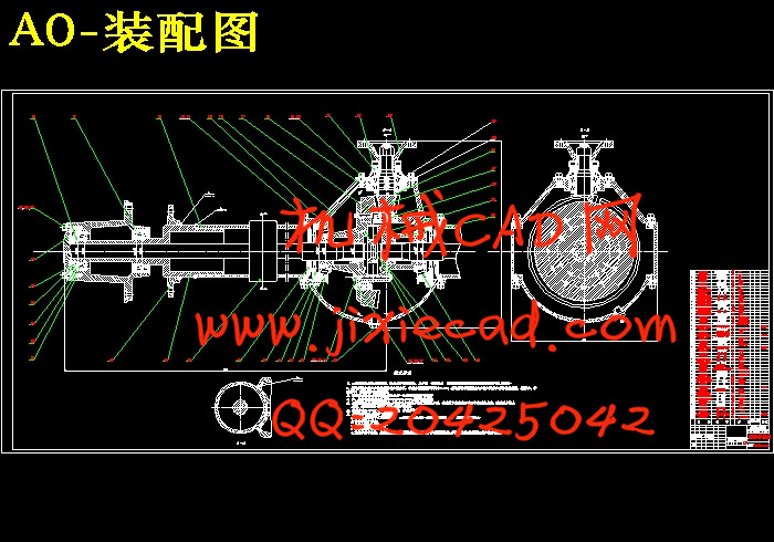
驱动桥是汽车的重要总成部件,也是汽车总成中的重要承载件,所以驱动桥的好坏直接影响着汽车整体的性能和零件的使用寿命等。驱动桥由主减速器、差速器、半轴及桥壳四部分组成,其基本功用是降速增扭,把发动机的动力传递给左右车轮,并使汽车在转向时保证左右车轮的差速功能,此外,还要承受作用于路面和车架或车厢之间的铅垂力、纵向力和横向力。
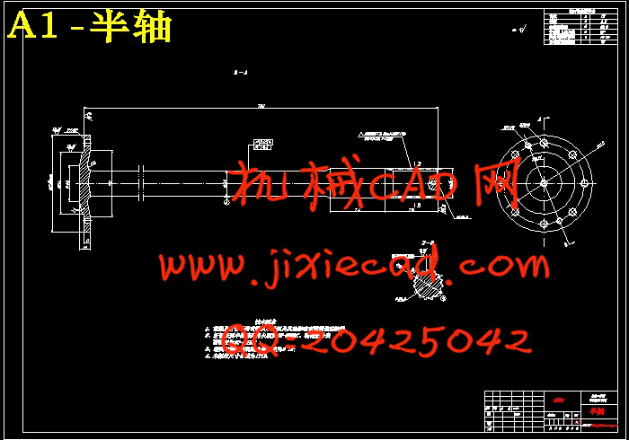
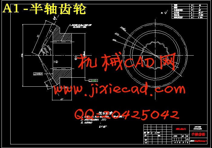
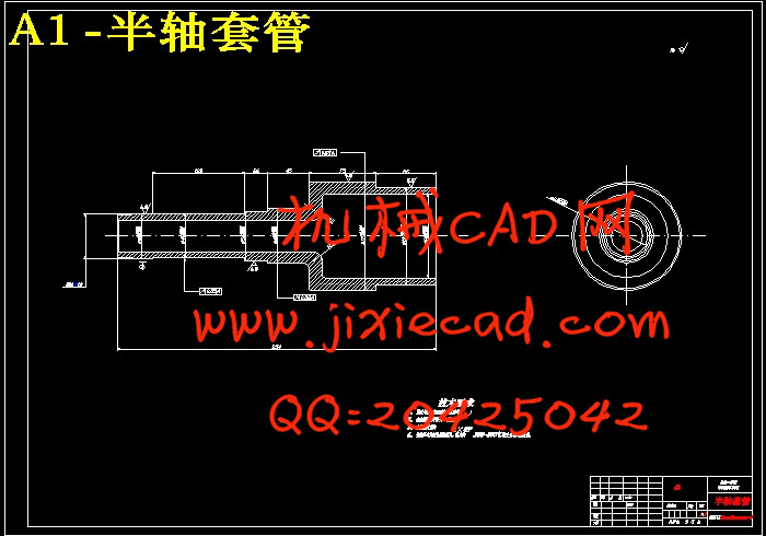
本设计首先论述了驱动桥的总体结构,在分析了驱动桥的结构形式及优缺点后确定总体设计方案:主减速器采用螺旋锥齿轮的单级主减速器,差速器采用圆锥行星齿轮差速器,半轴采用全浮式半轴,桥壳采用整体式桥壳。本设计主要完成了单级减速器、圆锥行星齿轮差速器、全浮式半轴的设计和桥壳的计算和校核及材料选取等工作。
关键词:整体式;驱动桥;主减速器;差速器;半轴;桥壳
ABSTRACT
Drive axle assembly is an important vehicle components and an important bearing in the vehicle assembly parts, so drive axle of a direct impact on overall vehicle performance and component life.Drive axle from the final drive, differential, axle and axle housing of four parts, the basic skills by using a spin-down twist, the engine's power passed to the left and right wheels, and to ensure the car when the steering wheel left and right differential function, in addition, but also act on the road and bear the car frame or between the vertical force, vertical force and lateral force.Discusses the design of the first drive axle of the overall structure of the analysis of the drive axle of the structure and determine the advantages and disadvantages of design options: with integral drive axle, main reducer reducer reducer type single stage, the main spiral bevel gear reducer gears, planetary gear differential with conical differential, axle with full floating type, with cast axle Integral axle.The design was completed for a single-stage reducer, planetary gear differential cone, full floating axle half shaft design and Check and material selection and so on.
Keywords: Integral; Drive Axle; Final Drive; Differential; Axle; Drive Axle Housing
目 录Drive axle assembly is an important vehicle components and an important bearing in the vehicle assembly parts, so drive axle of a direct impact on overall vehicle performance and component life.Drive axle from the final drive, differential, axle and axle housing of four parts, the basic skills by using a spin-down twist, the engine's power passed to the left and right wheels, and to ensure the car when the steering wheel left and right differential function, in addition, but also act on the road and bear the car frame or between the vertical force, vertical force and lateral force.Discusses the design of the first drive axle of the overall structure of the analysis of the drive axle of the structure and determine the advantages and disadvantages of design options: with integral drive axle, main reducer reducer reducer type single stage, the main spiral bevel gear reducer gears, planetary gear differential with conical differential, axle with full floating type, with cast axle Integral axle.The design was completed for a single-stage reducer, planetary gear differential cone, full floating axle half shaft design and Check and material selection and so on.
Keywords: Integral; Drive Axle; Final Drive; Differential; Axle; Drive Axle Housing
摘要 I
Abstract II
第1章 绪论 1
1.1 设计目的及意义 1
1.2 国内外驱动桥研究状况 1
1.3 设计主要内容 3
第2章 驱动桥的总体方案确定 4
2.1驱动桥的种类结构和设计要求 4
2.1.1汽车车桥的种类 4
2.1.2驱动桥的种类 4
2.1.3驱动桥结构组成 4
2.1.4 驱动桥设计要求 5
2.2 设计车型主要参数 5
2.3主减速器结构方案的确定 5
2.3.1 主减速器的齿轮类型及选择 5
2.3.2 主减速器的减速形式及选择 7
2.3.3 主减速器主从动锥齿轮的支承形式及安装方法 8
2.4 差速器结构方案的确定 9
2.5半轴的分类及方案的确定 10
2.6 桥壳的分类及方案的确定 10
2.7本章小结 11
第3章 主减速器设计 12
3.1概述 12
3.2主减速器齿轮参数的选择与强度计算 12
3.2.1 主减速器计算载荷的确定 12
3.2.2 主减速器齿轮参数的选择 13
3.2.3 主减速器齿轮强度计算 16
3.2.4 主减速器轴承计算 21
3.3主减速器齿轮材料及热处理 27
3.4主减速器的润滑 28
3.5 本章小结 28
第4章 差速器设计 29
4.1概述 29
4.2对称式圆锥行星齿轮差速器原理 29
4.3 对称式圆锥行星齿轮差速器的结构 30
4.4对称圆锥行星锥齿轮差速器的设计 31
4.4.1 差速器齿轮的基本参数选择 31
4.4.2 差速器齿轮的几何尺寸计算 33
4.4.3 差速器齿轮的强度计算 34
4.4.4 差速器齿轮的材料 35
4.5 本章小结 36
第5章 半轴设计 37
5.1概述 37
5.2半轴的设计与计算 37
5.2.1全浮式半轴的计算载荷的确定 37
5.2.2半轴杆部直径的初选 38
5.2.3 全浮式半轴强度计算 39
5.2.4 全浮式半轴花键强度计算 39
5.2.5 半轴材料与热处理 40
5.3 本章小结 41
第6章 驱动桥桥壳的设计 42
6.1概述 42
6.2桥壳的受力分析及强度计算 42
6.2.1 桥壳的静弯曲应力计算 42
6.2.2 在不平路面冲击载荷作用下桥壳的强度 44
6.2.3 汽车以最大牵引力行驶时的桥壳的强度计算 44
6.2.4 汽车紧急制动时的桥壳强度计算 46
6.2.5 汽车受最大侧向力时桥壳强度计算 47
6.3 本章小结 51
结论 52
参考文献 53
致谢 54


