设计简介
摘 要
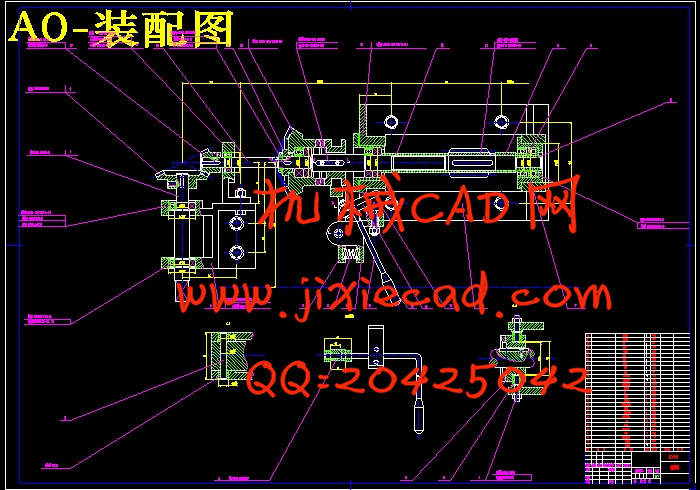
我本次设计的主要任务是倍捻机传动机构设计,该倍捻机主要适用于锦纶纤维的加捻。以往的倍捻机主要采用带锥形的卷装形式。本机改变了传统的卷绕形式,采用两头均为圆柱形的卷绕形式。这种圆柱形卷装没用束缚层,卷绕密度约比圆锥形大25~30%,增大了卷装容量。
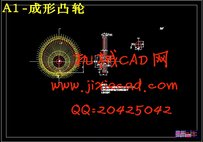
为了达到圆柱形卷绕的目的,在每一声将单程内,钢领板必须能够单独上升和下降,在整个卷绕过程中,钢领板的起始位置和终了位置保持不变,且钢领板上升和下降的速度也一样。由此,成形凸轮的表面曲线是两面对称的。
与以往的倍捻机相比,本机成形机构传动系统去掉了位叉、棘轮等改变钢领板升降动程的装置,简化了机构。而且采用链式对称传动,用弹簧代替平衡重锤,整个结构浑然一体,简单适用。本机还采用了气圈环控制气圈的大小,改善纱线张力,方便实用。
关键词:成形凸轮; 圆柱形卷装钢领板; 气圈环
Abstract
The main idea of my design is the transmit system of the shaping frame which is mainly suit for the twisting of the fiber.
The twisting machine in last days mainly used the cone-shaped winding formation. This machine has changed the tradition winding formation into a pillar-shaped one. This pillar-shaped winding formation has no constraint layer, and has a density 25~30% higher than cone-shaped one.
To get to the goal of the pillar-shaped winding, the lifting plate should be able to rise and fall undependently and in the whole winding process, the position of the lifting plate is in constant and the speed of rising and falling is the same. So the curve of the shaping cam is symmetric.
Comparing with the twisting machine of last days, the transmit system of the shaping frame of this machine is more simple. It uses symmetric chain to transmit, and uses spring instead of the balance weight.
Key words: the curve of the shaping cam; the lifting plate; pillar-shaped winding formation
目 录
1 绪论 1
2 倍捻机的工艺过程及主要技术参数 2
3 倍捻机的主要机构及其作用原理 3
3.1 喂给机构 3
3.2 输出机构 3
3.3 加捻卷绕机构 4
3.4 成型机构 5
4 设计方案 6
4.1 成形凸轮的设计 6
4.2 手动机构的设计 8
5 传动方案设计 10
5.1 传动方案的确定 10
5.2 传动比的分配 10
6 蜗杆传动设计 11
6.1 计算蜗杆轴的转速 11
6.2 计算蜗杆轴功率: 11
6.3 选择材料 11
6.4 确定主要参数 12
6.5 蜗轮的模数及蜗杆直径系数q. 12
6.6 验算蜗轮的圆周速度 13
13
6.7 求中心距a 13
6.8 校核齿根弯曲疲劳强度 13
6.9 蜗杆、蜗轮各部分尺寸的计算 14
6.10 精度等级的选择和公差,表面粗糙度的确定 15
6.11 蜗杆、蜗轮的结构设计 15
7 齿轮传动设计 16
7.1 选定齿轮类型、精度等级、材料及齿数 16
7.2 按齿面接触疲劳强度设计 16
7.2.1 确定公式各参数值 16
7.2.2 计算 17
7.3 校核齿根弯曲疲劳强度 18
7.4 结构设计 19
7.5 公差及表面粗糙度的确立 19
8 蜗杆轴的设计 20
8.1 初步估算轴的最小直径 20
20
8.2 轴的结构设计 20
8.2.1拟定轴上零件的装配方案 20
8.2.2根据轴向定位要求确定轴各段直径和长度 20
8.3 选择轴的材料 22
8.4 求轴上的载荷 22
9 链传动设计 24
9.1 链传动主要参数 24
9.1.1 选择链轮齿数 24
9.1.2 确定链条节距 24
9.1.3 确定中心距和链条长度 24
9.1.4 链轮的主要尺寸 24
9.2 链传动的张紧 24
9.3 链传动的润滑 24
10 总结 25
附录 25
参考文献 26
致谢 27
我本次设计的主要任务是倍捻机传动机构设计,该倍捻机主要适用于锦纶纤维的加捻。以往的倍捻机主要采用带锥形的卷装形式。本机改变了传统的卷绕形式,采用两头均为圆柱形的卷绕形式。这种圆柱形卷装没用束缚层,卷绕密度约比圆锥形大25~30%,增大了卷装容量。
为了达到圆柱形卷绕的目的,在每一声将单程内,钢领板必须能够单独上升和下降,在整个卷绕过程中,钢领板的起始位置和终了位置保持不变,且钢领板上升和下降的速度也一样。由此,成形凸轮的表面曲线是两面对称的。
与以往的倍捻机相比,本机成形机构传动系统去掉了位叉、棘轮等改变钢领板升降动程的装置,简化了机构。而且采用链式对称传动,用弹簧代替平衡重锤,整个结构浑然一体,简单适用。本机还采用了气圈环控制气圈的大小,改善纱线张力,方便实用。
关键词:成形凸轮; 圆柱形卷装钢领板; 气圈环
Abstract
The main idea of my design is the transmit system of the shaping frame which is mainly suit for the twisting of the fiber.
The twisting machine in last days mainly used the cone-shaped winding formation. This machine has changed the tradition winding formation into a pillar-shaped one. This pillar-shaped winding formation has no constraint layer, and has a density 25~30% higher than cone-shaped one.
To get to the goal of the pillar-shaped winding, the lifting plate should be able to rise and fall undependently and in the whole winding process, the position of the lifting plate is in constant and the speed of rising and falling is the same. So the curve of the shaping cam is symmetric.
Comparing with the twisting machine of last days, the transmit system of the shaping frame of this machine is more simple. It uses symmetric chain to transmit, and uses spring instead of the balance weight.
Key words: the curve of the shaping cam; the lifting plate; pillar-shaped winding formation
目 录
1 绪论 1
2 倍捻机的工艺过程及主要技术参数 2
3 倍捻机的主要机构及其作用原理 3
3.1 喂给机构 3
3.2 输出机构 3
3.3 加捻卷绕机构 4
3.4 成型机构 5
4 设计方案 6
4.1 成形凸轮的设计 6
4.2 手动机构的设计 8
5 传动方案设计 10
5.1 传动方案的确定 10
5.2 传动比的分配 10
6 蜗杆传动设计 11
6.1 计算蜗杆轴的转速 11
6.2 计算蜗杆轴功率: 11
6.3 选择材料 11
6.4 确定主要参数 12
6.5 蜗轮的模数及蜗杆直径系数q. 12
6.6 验算蜗轮的圆周速度
6.7 求中心距a 13
6.8 校核齿根弯曲疲劳强度 13
6.9 蜗杆、蜗轮各部分尺寸的计算 14
6.10 精度等级的选择和公差,表面粗糙度的确定 15
6.11 蜗杆、蜗轮的结构设计 15
7 齿轮传动设计 16
7.1 选定齿轮类型、精度等级、材料及齿数 16
7.2 按齿面接触疲劳强度设计 16
7.2.1 确定公式各参数值 16
7.2.2 计算 17
7.3 校核齿根弯曲疲劳强度 18
7.4 结构设计 19
7.5 公差及表面粗糙度的确立 19
8 蜗杆轴的设计 20
8.1 初步估算轴的最小直径
8.2 轴的结构设计 20
8.2.1拟定轴上零件的装配方案 20
8.2.2根据轴向定位要求确定轴各段直径和长度 20
8.3 选择轴的材料 22
8.4 求轴上的载荷 22
9 链传动设计 24
9.1 链传动主要参数 24
9.1.1 选择链轮齿数 24
9.1.2 确定链条节距 24
9.1.3 确定中心距和链条长度 24
9.1.4 链轮的主要尺寸 24
9.2 链传动的张紧 24
9.3 链传动的润滑 24
10 总结 25
附录 25
参考文献 26
致谢 27


