设计简介
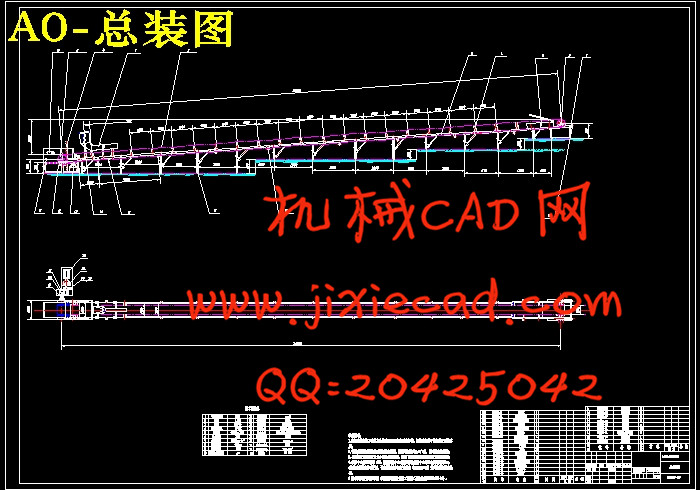
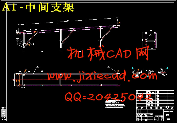
摘要:本文所设计的是槽形托辊带式输送机,其设计要求为:输送物料为原煤,输送量:500 吨/小时,输送长度:30 米,提升高度2.5米;堆积密度:900公斤/米3;物料在带面上的动堆积角为300,输送带速:2米/秒,上托辊槽形布置。设计中,其整体是一个倾斜的状态,上托辊都采用槽形布置;下(回程)托辊采用平行托辊。本输送机为向上运输物料,其倾斜角为3.80<150,所以采用小倾角设计。在设计带宽时,按照槽形布置来选择计算。在尾架的选取方面,采用螺旋拉紧装置尾架,使输送带能始终保持必要的张力。用Solidworks对连接轴进行有限元分析,得出其一般工作时的性能状态,并做出相应的调整。
目前,带式输送机正朝着长距离,高速度,低摩擦的方向发展,近年来出现的气垫式带式输送机就是其中的一个。在带式输送机的设计、制造以及应用方面,目前我国与国外先进水平相比仍有较大差距,国内在设计制造带式输送机过程中存在着很多不足。
关键词: 槽形托辊 带式输送机 输送带 有限元分析
Abstract: What is designed in this paper is slotted roller belt conveyor, the design requirements are: transport of materials: coal, transport capacity: 500 tons / hour, transmission length: 30 meters, 2.5 meters high upgrade; Bulk Density: 900 kg / m 3; materials in the dynamic accumulation of the surface with angle is 30, conveyor speed: 2 m / s, on the trough roller arrangement. Design of a tilt the overall state of the idler trough arrangement used; under the (return) the use of parallel idler rollers. When the materials are transport up through the conveyor, the tilt angle is 3.80 <150, so take the use of small-angle design. As the selection of the tailstock, we take the use of Tailstock screw tensioning device so that the conveyor system can always maintain the necessary tension. And Solidworks is used to do the finite element analysis on the connecting axis, to meet the required strength.
Today, long distance, high speed, low friction is the direction of belt conveyor’s development. Air cushion belt conveyor is one of them. At present, we still fall far short of abroad advanced technology in design, manufacture and using. There are a lot of wastes in the design of belt conveyor.
Keywords: slotted roller belt conveyor
conveyor idlers Finite Element Analysis
目 录
前言 …………………………………………………………………………………...(6)
1 带式输送机的概述…………………………………………………………(7)
1.1 带式输送机的应用………………………………………………………….(7)
1.2 带式输送机的工作原理 …………………………………………………..(8)
1.3 带式输送机的种类………………………………………………………….(8)
1.3.1 按承载能力分类……………………………………………………………..(9)
1.3.2 按可否移动分类……………………………………………………………..(9)
1.3.3 按输送带的结构形式分类…………………………………………………(9)
1.4 带式输送机的结构和布置形式……………………………………………(9)
1.5 带式输送机的性能……………………………………………....................(10)
1.6 带式输送机的发展状况…………………………………………………...(11)
2 带式输送机部件的选用………………………………………………...(12)
2.1 输送带………………………………………………………………………...(12)
2.1.1 输送带的分类………………………………………………………………..(12)
2.1.2 输送带的性能要求…………………………………………………………(14)
2.1.3 输送带的选用……………………………………………………………….(15)
2.2 驱动装置……………………………………………………………………..(18)
2.3 传动滚筒和改向滚筒………………………………………………………(18)
2.3.1 传动滚筒的作用及类型……………………………………………………(18)
2.3.2 传动滚筒的选型及设计……………………………………………………(19)
2.3.3 传动滚筒结构………………………………………………………………..(20)
2.3.4 改向滚筒………………………………………………………………………(20)
2.4 托辊……………………………………………………………………………(21)
2.5 机架和中间架………………………………………………………………..(24)
2.6 拉紧装置……………………………………………………………………...(25)
2.6.1 拉紧装置的作用…………………………………………………………….(25)
2.6.2 张紧装置在使用中应满足的要求……………………………………….(25)
2.6.2 拉紧装置的结构形式……………………………………………………..(26)
2.7 制动装置…………………………………………………………………….(28)
2.7.1 逆止器……………………………………………………………………….(28)
2.7.2 制动器……………………………………………………………………….(29)
2.8 清扫器……………………………………………………………………….(30)
2.8.1 头部清扫器…………………………………………………………………(30)
2.8.2 空段清扫器…………………………………………………………………(31)
2.9 卸料装置及导料槽……………………………………………………......(31)
2.9.1 卸料装置…………………………………………………………………….(31)
2.9.2 导料槽………………………………………………………………………..(33)
3 槽形托辊带式输送机的计算…………………………………………(33)
3.1 原始数据及工作条件…………………………………………… ..(33)
3.2 输送带选择计算………………………………………………...…(34)
3.2.1 选定带宽……………………………………………………………(34)
3.2.2 输送带上物料流横截面面积S的计算………………………...…(35)
3.3 圆周驱动力的计算……………………………………………...…(36)
3.3.1 圆周驱动力Fu…………………………………………………..…(36)
3.3.2 主要阻力F ……………………………………………………….(36)
3.3.3 附加阻力FN……………………………………………………..…(37)
3.3.4 主要特征阻力 ………………………………………………………….(37)
3.3.5 附加特种阻力Fs …………………………………………………………(38)
3.3.6 倾斜阻力Fst………………………………………………………………...(39)
3.4 输送带张力………………………………………………………………….(39)
3.4.1 输送带不打滑条件………………………………………………………...(39)
3.4.2 输送带下垂度校核………………………………………………………..(39)
3.4.3 各特性点张力………………………………………………………………(40)
3.5 传动滚筒轴功率…………………………………………………………..(40)
3.6 电动机功率和驱动装置组合…………………………………………….(41)
3.7 输送带选择计算……………………………………………………………(41)
3.7.1 织物芯输送带层数…………………………………………………………(42)
3.7.2 输送带厚度…………………………………………………………………..(42)
3.8 输送带总长度、总平方数和总质量…………………………………….(42)
3.8.1 输送带几何长度…………………………………………………………….(42)
3.8.2 输送带订货总长度…………………………………………………………(42)
3.8.3 输送带订货平方米………………………………………………………..(43)
3.8.4 输送带总质量…………………………………………………………..….(43)
3.9 托辊的选用计算……………………………………………………..…….(43)
3.10 输送带的强度校核…………………………………………………………(44)
3.11 传动滚筒轴的强度计算和校核………………………………………....(45)
3.11.1 传动滚筒的载荷集度……………………………………………….…….(45)
3.11.2 传动滚筒扭矩………………………………………………………………(46)
3.11.3 抗弯截面系数W…………………………………………………………..(46)
3.11.4 滚筒轴的弯曲强度………………………………………………………..(46)
3.12 传动滚筒轴承的寿命计算…………………………………………….…(46)
4 用solidworks对连接轴进行有限元分析……………….…...(48)
5 带式输送机皮带跑偏问题…………………………………………......(53)
小结……………………………………………………………………………………..(57)
参考文献…………………………………………………………………………….(58)
致 谢……………………………………………………………………………..(59)
目前,带式输送机正朝着长距离,高速度,低摩擦的方向发展,近年来出现的气垫式带式输送机就是其中的一个。在带式输送机的设计、制造以及应用方面,目前我国与国外先进水平相比仍有较大差距,国内在设计制造带式输送机过程中存在着很多不足。
关键词: 槽形托辊 带式输送机 输送带 有限元分析
Abstract: What is designed in this paper is slotted roller belt conveyor, the design requirements are: transport of materials: coal, transport capacity: 500 tons / hour, transmission length: 30 meters, 2.5 meters high upgrade; Bulk Density: 900 kg / m 3; materials in the dynamic accumulation of the surface with angle is 30, conveyor speed: 2 m / s, on the trough roller arrangement. Design of a tilt the overall state of the idler trough arrangement used; under the (return) the use of parallel idler rollers. When the materials are transport up through the conveyor, the tilt angle is 3.80 <150, so take the use of small-angle design. As the selection of the tailstock, we take the use of Tailstock screw tensioning device so that the conveyor system can always maintain the necessary tension. And Solidworks is used to do the finite element analysis on the connecting axis, to meet the required strength.
Today, long distance, high speed, low friction is the direction of belt conveyor’s development. Air cushion belt conveyor is one of them. At present, we still fall far short of abroad advanced technology in design, manufacture and using. There are a lot of wastes in the design of belt conveyor.
Keywords: slotted roller belt conveyor
conveyor idlers Finite Element Analysis
目 录
前言 …………………………………………………………………………………...(6)
1 带式输送机的概述…………………………………………………………(7)
1.1 带式输送机的应用………………………………………………………….(7)
1.2 带式输送机的工作原理 …………………………………………………..(8)
1.3 带式输送机的种类………………………………………………………….(8)
1.3.1 按承载能力分类……………………………………………………………..(9)
1.3.2 按可否移动分类……………………………………………………………..(9)
1.3.3 按输送带的结构形式分类…………………………………………………(9)
1.4 带式输送机的结构和布置形式……………………………………………(9)
1.5 带式输送机的性能……………………………………………....................(10)
1.6 带式输送机的发展状况…………………………………………………...(11)
2 带式输送机部件的选用………………………………………………...(12)
2.1 输送带………………………………………………………………………...(12)
2.1.1 输送带的分类………………………………………………………………..(12)
2.1.2 输送带的性能要求…………………………………………………………(14)
2.1.3 输送带的选用……………………………………………………………….(15)
2.2 驱动装置……………………………………………………………………..(18)
2.3 传动滚筒和改向滚筒………………………………………………………(18)
2.3.1 传动滚筒的作用及类型……………………………………………………(18)
2.3.2 传动滚筒的选型及设计……………………………………………………(19)
2.3.3 传动滚筒结构………………………………………………………………..(20)
2.3.4 改向滚筒………………………………………………………………………(20)
2.4 托辊……………………………………………………………………………(21)
2.5 机架和中间架………………………………………………………………..(24)
2.6 拉紧装置……………………………………………………………………...(25)
2.6.1 拉紧装置的作用…………………………………………………………….(25)
2.6.2 张紧装置在使用中应满足的要求……………………………………….(25)
2.6.2 拉紧装置的结构形式……………………………………………………..(26)
2.7 制动装置…………………………………………………………………….(28)
2.7.1 逆止器……………………………………………………………………….(28)
2.7.2 制动器……………………………………………………………………….(29)
2.8 清扫器……………………………………………………………………….(30)
2.8.1 头部清扫器…………………………………………………………………(30)
2.8.2 空段清扫器…………………………………………………………………(31)
2.9 卸料装置及导料槽……………………………………………………......(31)
2.9.1 卸料装置…………………………………………………………………….(31)
2.9.2 导料槽………………………………………………………………………..(33)
3 槽形托辊带式输送机的计算…………………………………………(33)
3.1 原始数据及工作条件…………………………………………… ..(33)
3.2 输送带选择计算………………………………………………...…(34)
3.2.1 选定带宽……………………………………………………………(34)
3.2.2 输送带上物料流横截面面积S的计算………………………...…(35)
3.3 圆周驱动力的计算……………………………………………...…(36)
3.3.1 圆周驱动力Fu…………………………………………………..…(36)
3.3.2 主要阻力F
3.3.3 附加阻力FN……………………………………………………..…(37)
3.3.4 主要特征阻力
3.3.5 附加特种阻力Fs
3.3.6 倾斜阻力Fst………………………………………………………………...(39)
3.4 输送带张力………………………………………………………………….(39)
3.4.1 输送带不打滑条件………………………………………………………...(39)
3.4.2 输送带下垂度校核………………………………………………………..(39)
3.4.3 各特性点张力………………………………………………………………(40)
3.5 传动滚筒轴功率…………………………………………………………..(40)
3.6 电动机功率和驱动装置组合…………………………………………….(41)
3.7 输送带选择计算……………………………………………………………(41)
3.7.1 织物芯输送带层数…………………………………………………………(42)
3.7.2 输送带厚度…………………………………………………………………..(42)
3.8 输送带总长度、总平方数和总质量…………………………………….(42)
3.8.1 输送带几何长度…………………………………………………………….(42)
3.8.2 输送带订货总长度…………………………………………………………(42)
3.8.3 输送带订货平方米………………………………………………………..(43)
3.8.4 输送带总质量…………………………………………………………..….(43)
3.9 托辊的选用计算……………………………………………………..…….(43)
3.10 输送带的强度校核…………………………………………………………(44)
3.11 传动滚筒轴的强度计算和校核………………………………………....(45)
3.11.1 传动滚筒的载荷集度……………………………………………….…….(45)
3.11.2 传动滚筒扭矩………………………………………………………………(46)
3.11.3 抗弯截面系数W…………………………………………………………..(46)
3.11.4 滚筒轴的弯曲强度………………………………………………………..(46)
3.12 传动滚筒轴承的寿命计算…………………………………………….…(46)
4 用solidworks对连接轴进行有限元分析……………….…...(48)
5 带式输送机皮带跑偏问题…………………………………………......(53)
小结……………………………………………………………………………………..(57)
参考文献…………………………………………………………………………….(58)
致 谢……………………………………………………………………………..(59)


