设计简介
摘 要:如今,液压传动是一门比较成熟的技术,已广泛应用于机械制造、工程机械、农业机械、汽车制造以及锻压等机械行业。而其在实现高压、高速、大功率、高效率、低噪声、经久耐用,高度集成化等各项要求方面的显著优势使得这门技术有着更加广阔的发展前景。
本文在对液压传动发展和液压传动的工作原理作了一个简要说明的同时,更对液压技术在锻压机械中的一个典型应用——单柱液压机的液压系统进行了全面的设计计算。其内容主要包括:
Ⅰ 液压传动系统方案的分析、比较和确定;
Ⅱ 确定并绘制系统原理图;
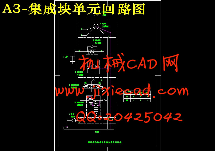
Ⅲ 集成块单元回路图的绘制;
Ⅳ 液压系统中各主要参数的计算、圆整及校核;
Ⅴ 各种液压元件的选择;
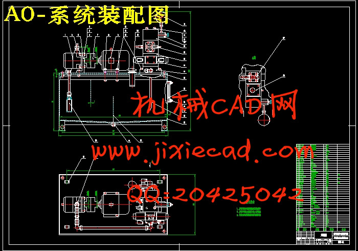
Ⅵ 设计并绘制以集成块联接方式而成的系统装配图;
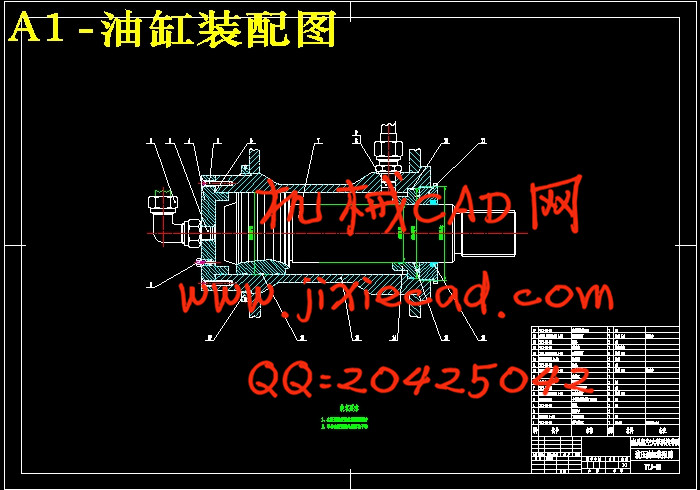
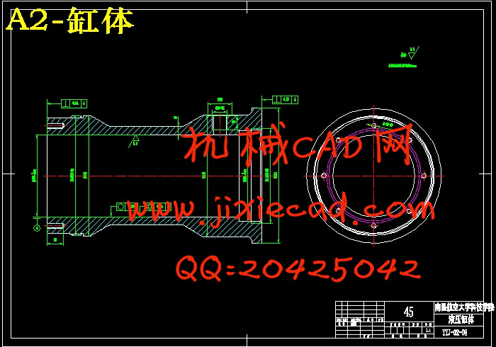
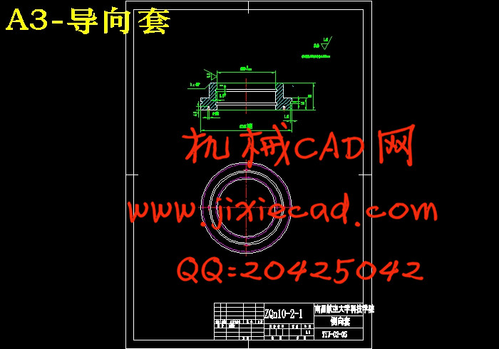
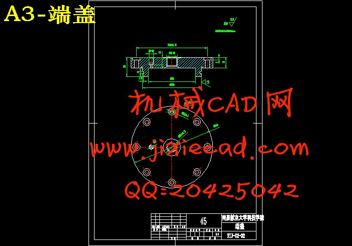
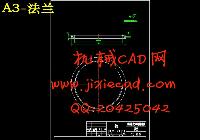
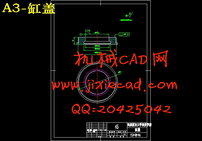
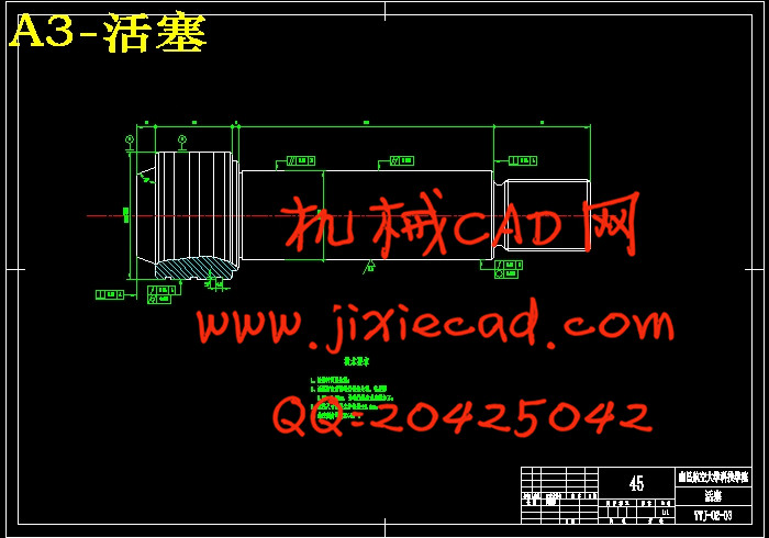
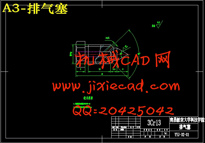
在单柱液压机液压系统执行元件液压缸的设计中,利用在前文系统设计中所校核过的如活塞直径D(ΦAL)、活塞杆直径d(ΦMM)等参数,我们对液压油缸的各主要零部件进行了详细的结构设计,并绘制了它们的零件图及液压油缸装配图。
在本设计中,所有图纸均使用绘图软件AutoCAD绘制而成,使得图纸更加清晰,一目了然。
关键字:单柱液压机;液压系统设计;液压油缸;AutoCAD
Ⅰ Analysing, comparing and confirming the project of hydraulic drive;
Ⅱ Confirming and drawing the system blueprint;
Ⅲ Drawing a blueprint of the cell loop of the integration block;
Ⅳ Accounting, checking and normalizing the mainly parameter in the hydraulic system
Ⅴ Choosing the different kinds of hydraulic component
Ⅵ Designing how to rig out all the parts of the system and then draw a blueprint to reflect it.
In the design of the working part of the hydraulic system, cylinder, we have do a particular frame design in using the parameter as the diameter of the piston D(ΦAL) and the diameter of the pole d(ΦMM).
In this project, to make blueprint more clearly and even be clear at a glance, we draw the entire blueprint in software AutoCAD.
Key words: Single Column Hydraulic Presses; The Design of Hydraulic System; Hydraulic cylinder; AutoCAD
1、概述 1
1.1 液压传动发展概况 1
1.2 液压传动的工作原理及组成部分 1
1.2.1 液压传动的工作原理 1
1.2.2 液压传动的组成部分 2
1.3 液压传动的优缺点 3
2、液压系统设计 4
2.1 明确设计要求,制定基本方案 4
2.1.1 设计要求 4
2.1.2 制定液压系统基本方案 4
2.2 液压系统各液压元件的确定 6
2.2.1 液压介质的选择 6
2.2.2 拟定液压系统图 6
2.3 液压系统主要参数计算 8
2.3.1 选系统工作压力 8
2.3.2 液压缸主要参数的确定 8
2.3.3 液压缸强度校核 8
2.3.4 液压缸稳定性校核 10
2.3.5 计算液压缸实际所需流量 12
2.3.6 绘制液压缸工况图 14
2.4 液压阀的选择 15
2.4.1 液压阀的作用 15
2.4.2 液压阀的基本要求 15
2.4.3 液压阀的选择 15
34DF30-E10B-D 15
3 液压泵站及其辅助装置 16
3.1 液压泵站 16
3.1.1 液压泵站概述及液压泵站油箱容量系列标准 16
3.1.2 各系列液压泵站的简述 17
3.2 液压泵 18
3.2.1 液压泵的选择 18
3.2.2 液压泵装置 20
3.3 电动机功率的确定 21
3.4 液压管件的确定 22
3.4.1 油管内径确定 22
3.4.2 管接头 22
3.5 滤油器的选择 23
3.5.1 滤油器的作用及过滤精度 23
3.5.2 选用和安装 23
3.6 油箱及其辅件的确定 23
3.6.1 油箱 23
3.6.2 空气滤清器 26
3.6.3 油标 26
4 液压缸的设计计算 27
4.1 液压缸的基本参数的确定 27
4.2 液压缸主要零件的结构、材料及技术要求 27
4.2.1 缸体 27
4.3 缸盖 30
4.3.1 缸盖的材料 30
4.4 活塞 30
4.4.1 活塞与活塞杆的联接型式 30
4.4.2 活塞与缸体的密封 31
4.4.3 活塞的材料 31
4.4.4 活塞的技术要求 31
4.5 活塞杆 32
4.5.1 端部结构 32
4.5.2 端部尺寸 32
4.5.3 活塞杆结构 33
4.5.4 活塞杆材料 34
4.5.5 活塞杆的技术要求 34
4.6 活塞杆的导向、密封和防尘 34
4.6.1 导向套 34
4.6.2 杆的密封与防尘 35
4.7 液压缸的缓冲装置 35
4.8 液压缸的排气装置 35
4.9 液压缸安装联接部分的型式 36
4.9.1 液压缸进出油口的联接 36
4.9.2 液压缸的安装方式 36
结 论 37
致 谢 38
参 考 文 献 39
本文在对液压传动发展和液压传动的工作原理作了一个简要说明的同时,更对液压技术在锻压机械中的一个典型应用——单柱液压机的液压系统进行了全面的设计计算。其内容主要包括:
Ⅰ 液压传动系统方案的分析、比较和确定;
Ⅱ 确定并绘制系统原理图;
Ⅲ 集成块单元回路图的绘制;
Ⅳ 液压系统中各主要参数的计算、圆整及校核;
Ⅴ 各种液压元件的选择;
Ⅵ 设计并绘制以集成块联接方式而成的系统装配图;
在单柱液压机液压系统执行元件液压缸的设计中,利用在前文系统设计中所校核过的如活塞直径D(ΦAL)、活塞杆直径d(ΦMM)等参数,我们对液压油缸的各主要零部件进行了详细的结构设计,并绘制了它们的零件图及液压油缸装配图。
在本设计中,所有图纸均使用绘图软件AutoCAD绘制而成,使得图纸更加清晰,一目了然。
关键字:单柱液压机;液压系统设计;液压油缸;AutoCAD
Abstract:Nowadays, hydraulic drive is a technique becoming mature, what has been applied in Manufacture, Engineering Machinery, Farm Machinery, Car Manufacturing, and Forging Presses etc. Moreover, it has a so salient advantage in actualize high pressure, high speed, hight-power, hight efficiency, low yawp, longevity and hight integration that it could develope much faster then others.
After the phylogeny of the hydraulic drive and the working theory have been introduced in this paper, we have do a fully design for the system of the single column hydraulic presses which is a type application in Forging Presses.It includes:Ⅰ Analysing, comparing and confirming the project of hydraulic drive;
Ⅱ Confirming and drawing the system blueprint;
Ⅲ Drawing a blueprint of the cell loop of the integration block;
Ⅳ Accounting, checking and normalizing the mainly parameter in the hydraulic system
Ⅴ Choosing the different kinds of hydraulic component
Ⅵ Designing how to rig out all the parts of the system and then draw a blueprint to reflect it.
In the design of the working part of the hydraulic system, cylinder, we have do a particular frame design in using the parameter as the diameter of the piston D(ΦAL) and the diameter of the pole d(ΦMM).
In this project, to make blueprint more clearly and even be clear at a glance, we draw the entire blueprint in software AutoCAD.
Key words: Single Column Hydraulic Presses; The Design of Hydraulic System; Hydraulic cylinder; AutoCAD
1、概述 1
1.1 液压传动发展概况 1
1.2 液压传动的工作原理及组成部分 1
1.2.1 液压传动的工作原理 1
1.2.2 液压传动的组成部分 2
1.3 液压传动的优缺点 3
2、液压系统设计 4
2.1 明确设计要求,制定基本方案 4
2.1.1 设计要求 4
2.1.2 制定液压系统基本方案 4
2.2 液压系统各液压元件的确定 6
2.2.1 液压介质的选择 6
2.2.2 拟定液压系统图 6
2.3 液压系统主要参数计算 8
2.3.1 选系统工作压力 8
2.3.2 液压缸主要参数的确定 8
2.3.3 液压缸强度校核 8
2.3.4 液压缸稳定性校核 10
2.3.5 计算液压缸实际所需流量 12
2.3.6 绘制液压缸工况图 14
2.4 液压阀的选择 15
2.4.1 液压阀的作用 15
2.4.2 液压阀的基本要求 15
2.4.3 液压阀的选择 15
34DF30-E10B-D 15
3 液压泵站及其辅助装置 16
3.1 液压泵站 16
3.1.1 液压泵站概述及液压泵站油箱容量系列标准 16
3.1.2 各系列液压泵站的简述 17
3.2 液压泵 18
3.2.1 液压泵的选择 18
3.2.2 液压泵装置 20
3.3 电动机功率的确定 21
3.4 液压管件的确定 22
3.4.1 油管内径确定 22
3.4.2 管接头 22
3.5 滤油器的选择 23
3.5.1 滤油器的作用及过滤精度 23
3.5.2 选用和安装 23
3.6 油箱及其辅件的确定 23
3.6.1 油箱 23
3.6.2 空气滤清器 26
3.6.3 油标 26
4 液压缸的设计计算 27
4.1 液压缸的基本参数的确定 27
4.2 液压缸主要零件的结构、材料及技术要求 27
4.2.1 缸体 27
4.3 缸盖 30
4.3.1 缸盖的材料 30
4.4 活塞 30
4.4.1 活塞与活塞杆的联接型式 30
4.4.2 活塞与缸体的密封 31
4.4.3 活塞的材料 31
4.4.4 活塞的技术要求 31
4.5 活塞杆 32
4.5.1 端部结构 32
4.5.2 端部尺寸 32
4.5.3 活塞杆结构 33
4.5.4 活塞杆材料 34
4.5.5 活塞杆的技术要求 34
4.6 活塞杆的导向、密封和防尘 34
4.6.1 导向套 34
4.6.2 杆的密封与防尘 35
4.7 液压缸的缓冲装置 35
4.8 液压缸的排气装置 35
4.9 液压缸安装联接部分的型式 36
4.9.1 液压缸进出油口的联接 36
4.9.2 液压缸的安装方式 36
结 论 37
致 谢 38
参 考 文 献 39


