设计简介
焊接机器人设计
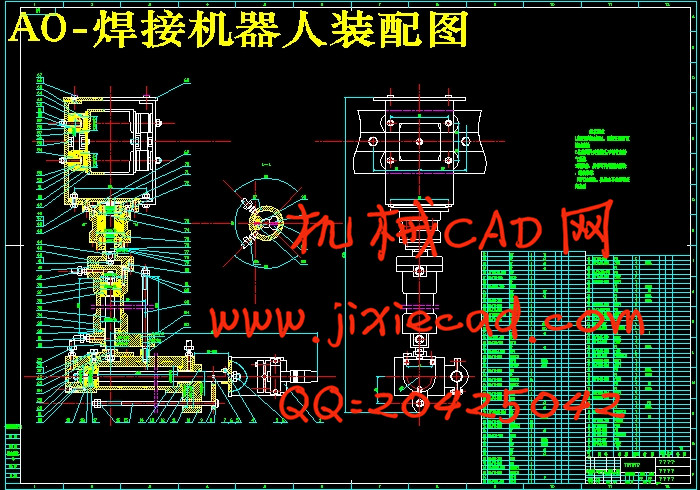
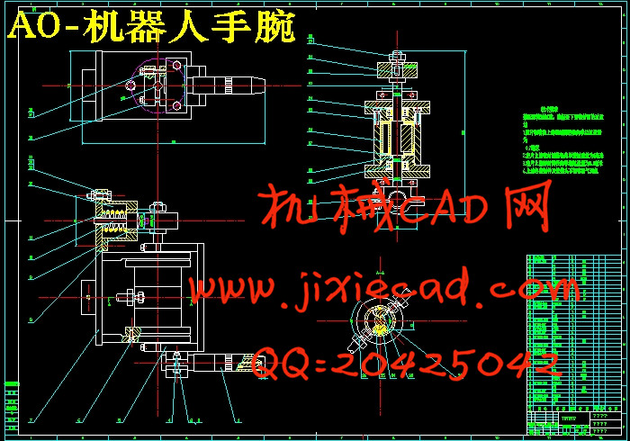
本设计的重点是运用机械原理和机械制造装备设计方法设计焊接机器人的实践和方法。本次设计,是在了解焊接机器人在国内外现状的基础上,进而掌握焊接机器人内部结构和工作原理,并对手臂和腕部进行结构设计。合理布置了液压缸。同时了解机器人机械系统运动学及运动控制学。为工业上焊接机器人的设计提供理论参考、设计参考和数据参考,为工业设计者提供设计理论和设计实践的参考。该机器人具有刚性好,位置精度高、运行平稳的特点。
关键字:焊接机器人 液压系统 机械机构设计
The focus of this design is the use of mechanical theory and design of machinery and equipment design and methods of practice welding robot.The design of the welding robot in understanding the basis of the status quo at home and abroad, and then grasp the welding robot and working principle of the internal structure, and structural design of the arm and wrist.Rational arrangement of the hydraulic cylinder.At the same time understand the robot mechanical system kinematics and motion control study.For the design of industrial welding robots to provide a theoretical reference, reference and data reference design for industrial designers and design practice, design theory reference.The robot has a good rigidity, high precision location, stable characteristics.
Keyword:Welding robot;hydraulic system;mechanical structure design
Abstract II
第1章 引言 1
第2章 焊接机器人的总体方案 3
2.1 总体设计的思路 3
2.2 自由度和坐标系的选择 3
2.3 传动方案论证 4
2.4 焊接机器人的组成 6
2.4.1 执行机构 6
2.4.2 控制系统分类 8
2.5 焊接机器人的技术参数 8
2.6 本章小结 8
第3章 腕部结构的设计及计算 10
3.1 腕部设计的基本要求 10
3.2 腕部结构及选择 10
3.2.1 典型的腕部结构 10
3.2.2 腕部结构和驱动结构的选择 10
3.3 腕部结构设计计算 11
3.3.1 腕部驱动力计算 11
3.3.2 腕部驱动液压缸的计算 11
3.4 液压缸盖螺钉的计算 12
3.5 动片和输出轴间的连接螺钉 13
3.6 本章小结 13
第4章 臂部结构的设计及计算 15
4.1 臂部设计的基本要求 15
4.2 手臂的典型机构以及结构的选择 16
4.2.1 手臂的典型运动机构 16
4.2.2 手臂运动机构的选择 16
4.3 手臂直线运动的驱动力计算 17
4.3.1 手臂摩擦力的分析与计算 17
4.3.2 手臂惯性力的计算 18
4.3.3 密封装置的摩擦阻力 18
4.4 液压缸工作压力和结构的确定 18
4.5活塞杆的计算校核 19
4.6 本章小结 20
第5章 机身结构的设计及计算 21
5.1机身的整体设计 21
5.2机身回转机构的设计计算 22
5.3 机身升降机构的计算 23
5.3.1 手臂偏重力矩的计算 23
5.3.2 升降不自锁条件分析计算 24
5.3.3 手臂做升降运动的液压缸驱动力的计算 24
5.4 轴承的选择分析 25
5.5 本章小结 25
总结 26
致谢 27
参考文献 28
摘 要
随着科技的发展和工业需求的增加,焊接技术在工业生产中所占据的分量越来越大,而且焊接技术的优良程度直接影响着零件或产品的质量。国内焊接机器人应用虽已具有一定规模,但与我国焊接生产总体需求相差甚远。因此,大力研究并推广焊接机器人技术势在必行。本设计的重点是运用机械原理和机械制造装备设计方法设计焊接机器人的实践和方法。本次设计,是在了解焊接机器人在国内外现状的基础上,进而掌握焊接机器人内部结构和工作原理,并对手臂和腕部进行结构设计。合理布置了液压缸。同时了解机器人机械系统运动学及运动控制学。为工业上焊接机器人的设计提供理论参考、设计参考和数据参考,为工业设计者提供设计理论和设计实践的参考。该机器人具有刚性好,位置精度高、运行平稳的特点。
关键字:焊接机器人 液压系统 机械机构设计
Abstract
With the development of technology and the increase in industrial demand, welding in industrial production occupied more and more weight, and excellent welding technology directly affects the degree of the quality of parts or products.Although the domestic application of welding robot with a certain scale, but falls far short of the overall demand for welding.Therefore, great efforts to study and promote the welding robot technology is imperative.The focus of this design is the use of mechanical theory and design of machinery and equipment design and methods of practice welding robot.The design of the welding robot in understanding the basis of the status quo at home and abroad, and then grasp the welding robot and working principle of the internal structure, and structural design of the arm and wrist.Rational arrangement of the hydraulic cylinder.At the same time understand the robot mechanical system kinematics and motion control study.For the design of industrial welding robots to provide a theoretical reference, reference and data reference design for industrial designers and design practice, design theory reference.The robot has a good rigidity, high precision location, stable characteristics.
Keyword:Welding robot;hydraulic system;mechanical structure design
目 录
摘 要 IAbstract II
第1章 引言 1
第2章 焊接机器人的总体方案 3
2.1 总体设计的思路 3
2.2 自由度和坐标系的选择 3
2.3 传动方案论证 4
2.4 焊接机器人的组成 6
2.4.1 执行机构 6
2.4.2 控制系统分类 8
2.5 焊接机器人的技术参数 8
2.6 本章小结 8
第3章 腕部结构的设计及计算 10
3.1 腕部设计的基本要求 10
3.2 腕部结构及选择 10
3.2.1 典型的腕部结构 10
3.2.2 腕部结构和驱动结构的选择 10
3.3 腕部结构设计计算 11
3.3.1 腕部驱动力计算 11
3.3.2 腕部驱动液压缸的计算 11
3.4 液压缸盖螺钉的计算 12
3.5 动片和输出轴间的连接螺钉 13
3.6 本章小结 13
第4章 臂部结构的设计及计算 15
4.1 臂部设计的基本要求 15
4.2 手臂的典型机构以及结构的选择 16
4.2.1 手臂的典型运动机构 16
4.2.2 手臂运动机构的选择 16
4.3 手臂直线运动的驱动力计算 17
4.3.1 手臂摩擦力的分析与计算 17
4.3.2 手臂惯性力的计算 18
4.3.3 密封装置的摩擦阻力 18
4.4 液压缸工作压力和结构的确定 18
4.5活塞杆的计算校核 19
4.6 本章小结 20
第5章 机身结构的设计及计算 21
5.1机身的整体设计 21
5.2机身回转机构的设计计算 22
5.3 机身升降机构的计算 23
5.3.1 手臂偏重力矩的计算 23
5.3.2 升降不自锁条件分析计算 24
5.3.3 手臂做升降运动的液压缸驱动力的计算 24
5.4 轴承的选择分析 25
5.5 本章小结 25
总结 26
致谢 27
参考文献 28


