设计简介
摘要
我国商用车的制造已经成熟化,在亚洲和非洲开辟出新市场。驱动桥作为商用车底盘中关键部分,其设计要精益求精。
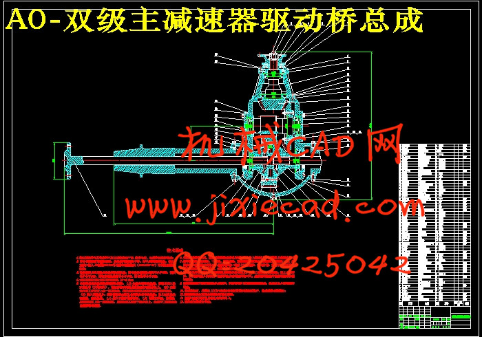
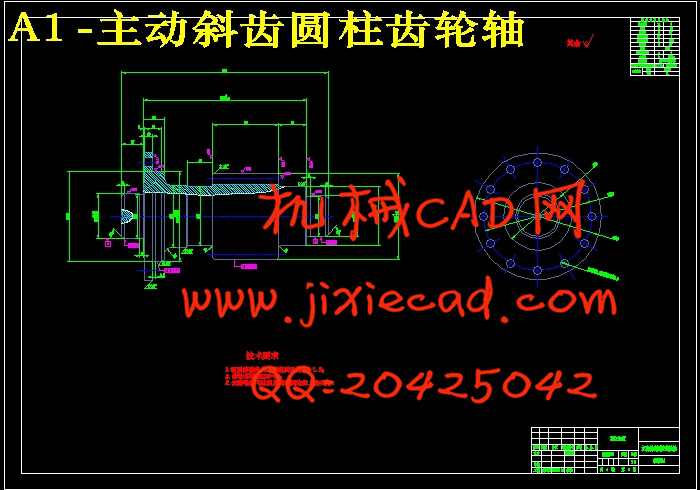
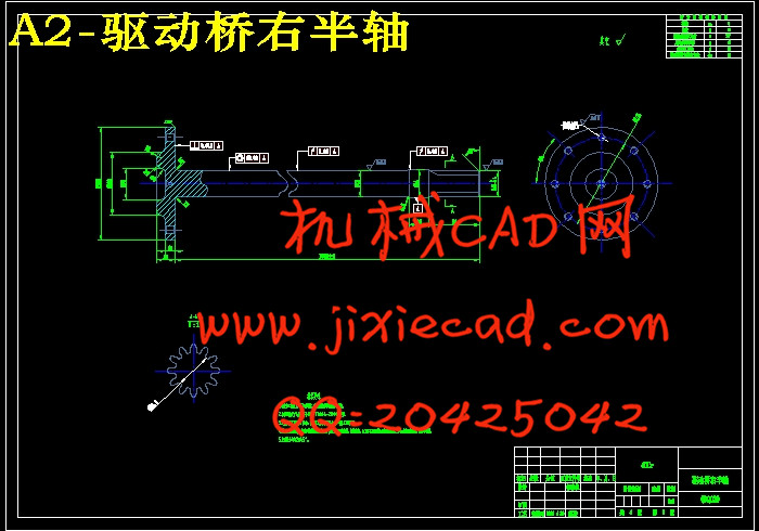
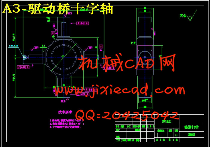
本设计对国产商用车福田欧马可5系底盘进行了分析,决定对其驱动后桥做优化设计。先查阅多本教材及图书馆参考书籍,对驱动桥内主要部分一一分析,选型后选择合理数据,计算校核。其次根据计算所得出的各零部件参数,用自己熟悉的制图软件绘制零件图,再自己设计出装配图。通过制图来找出自己在计算设计中的失误之处,修改所得参数并修改图纸。使用UG10.0辅助、三维建模,并用其自带高级仿真模块对桥壳有限元分析。
本设计的驱动桥可以安装到大部分中型汽车上,对驱动桥的设计和优化做提供了案例。
关键词:主减速器;桥壳;半轴;桥壳;驱动桥;有限元分析
Abstract
The manufacture of commercial vehicles in China has matured and opened up new markets in Asia and Africa. As a important part of the chassis of a commercial vehicle, the drive axle must be designed critically.
The design of the domestic commercial vehicle Futian Ouma 5 Series chassis was analyzed and it was decided to optimize the design of its rear axle. First consult multiple textbooks and library reference books, analyze the main parts of the drive axle one by one, select reasonable data after the selection, and calculate and verify. Secondly, according to the calculated parameters of each part, use the familiar drawing software to draw the parts drawing, and then design the assembly drawing by yourself. Use cartography to find out where your mistakes are in the calculation design, modify the resulting parameters, and modify the drawings. Use UG10.0 assisted, three-dimensional modeling, and use its own advanced simulation module for finite element analysis of the axle housing.
The design of the drive axle can be installed on most medium-sized vehicles, providing a case for the design and optimization of the drive axle.
Key words:Main reducer; axle housing; half shaft; axle housing; drive axle;Finite element analysis
目录
前言 1
1驱动桥总体布置方案分析 2
1.1概述 2
1.2设计主要参数 2
1.2.1主减速比的计算 3
1.2.2一挡传动比的确定 4
1.3驱动桥结构形式的选择 5
2主减速器设计 6
2.1主减速器结构方案分析 6
2.1.1主减速器齿轮的类型 6
2.1.2双级主减速器的结构方案 6
2.1.3主减速器主、从动锥齿轮的支承方案 7
2.2主减速器比的分配 7
2.3第一级减速器锥齿轮的设计 8
2.3.1主减速器齿轮计算载荷的确定 8
2.3.2锥齿轮主要参数的选择 10
2.3.3主减速器锥齿轮的强度校核 14
2.3.4锥齿轮的材料选择 18
2.4第二级减速器斜齿圆柱齿轮的设计 18
2.4.1斜齿圆柱齿轮主要参数的选择 18
2.4.2斜齿圆柱齿轮的强度计算 20
2.4.3斜齿圆柱齿轮的材料选择 21
3差速器设计 23
3.1差速器结构形式的确定 23
3.2差速器齿轮的设计 23
3.2.1差速器齿轮的参数选择 23
3.2.2差速器齿轮的强度计算 26
3.2.3差速器齿轮的材料选择 26
4车轮传动装置设计 27
4.1半轴的型式选择 27
4.2半轴的设计计算 27
4.2.1半轴的直径及长度选择 27
4.2.2半轴的强度计算 28
4.2.3半轴的材料选择 28
5驱动桥的桥壳设计 29
5.1桥壳结构型式的选择 29
5.2桥壳的尺寸选择及静弯曲应力计算 29
6驱动桥三维造型设计及仿真分析 32
6.1驱动桥零件的建模 32
6.1.1第一级减速器锥齿轮的建模及啮合装配 32
6.1.2第二级斜齿圆柱齿轮的建模及啮合装配 39
6.1.3行星齿轮和半轴齿轮的建模及啮合 43
6.1.4半轴的建模 45
6.1.5驱动桥桥壳的建模 46
6.2驱动桥零件的装配及仿真 52
6.2.1驱动桥各部分零件的装配 52
6.2.2驱动桥运动仿真分析 56
6.3驱动桥桥壳的有限元分析 58
6.3.1最大垂向力分析 60
6.3.2最大牵引力分析 62
6.3.3最大制动力分析 64
6.3.4最大侧向力分析 66
7驱动桥技术经济性分析 69
8结论 70
致谢 71
参考文献 72


