设计简介
摘 要
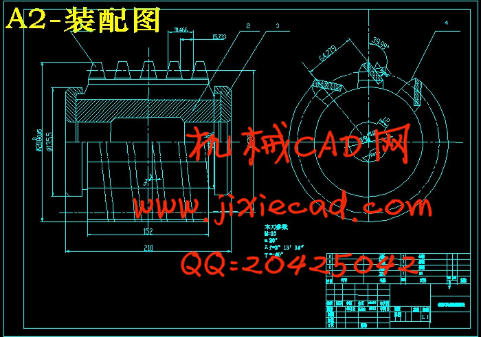
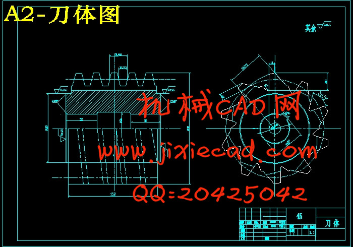
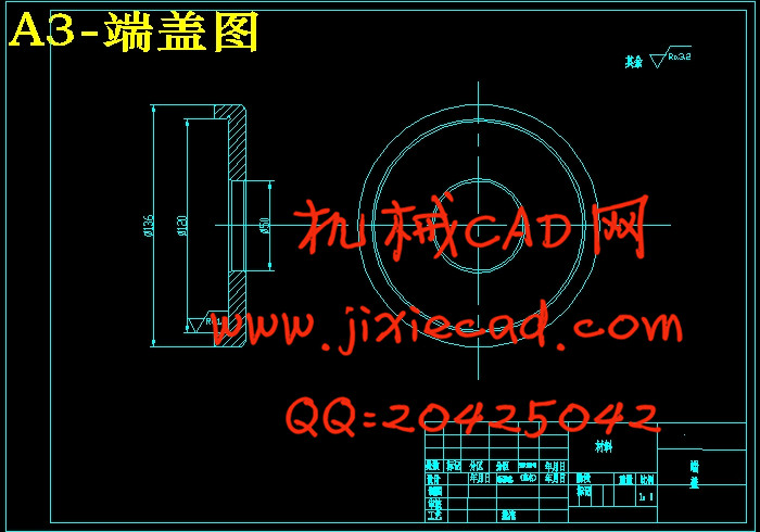
齿轮是现代机械传动的重要组成部分,许多领域都在广泛的运用齿轮传动,因此对齿轮的精度和加工效率要求也越来越高。就目前而言,很多要求高精度的齿轮都是磨削加工出来的,然而对于一些大型的工件,不能使用磨削,因此为了改善这样的情况,就采用刮削代替磨削,这样既满足了精度要求又提高了加工效率。本设计是对滚刀的蜗杆造型、齿形、工作原理进行了分析,并设计了齿形误差检测程序。设计的基本想法是:在刀体上开出容屑槽,把刀体和刀片进行热处理,之后把刀片沿着半径方向压入刀体槽内,再之后磨两头的轴台,把加热之后的端盖套上去,冷却之后紧紧压住刀片,装配完成后就精加工齿面。本设计用的是硬质合金刀片,能实现以刮代磨,节省工时,大大提高加工效率。
关键词:滚刀、蜗杆造型、齿形设计、程序检测
ABSTRACT
Contents of the abstract. Times New Roman.
Gear is an important part of modern mechanical transmission, many areas are widely used in gear transmission, so the accuracy of this round and processing efficiency requirements are getting higher and higher. For now, many require high precision gears are grinding out, but for some large parts, can not use grinding, so in order to improve this situation, the use of scraping instead of grinding, the use of fabricated structure, This is to meet the accuracy requirements and improve the processing efficiency. The design of the hob is the horn shape, tooth shape, the working principle of the analysis, and the design of the tooth error detection program. The basic idea of the design is: the chip body out of the chip flute, the blade and the blade heat treatment, then the blade along the radial direction into the body groove, and then after grinding two ends of the shaft, the heating After the end cap sets up, after cooling tightly pressed the blade, the assembly is finished after finishing the tooth surface. The design is a carbide blade, to achieve scraping grinding, saving man-hours, greatly improving the processing efficiency.
Key words:Gear hob, worm shape, tooth shape design, program test
|
2 |
齿轮加工概述.................................................................................................... |
|
3 |
|
2.1 |
齿轮加工方法......................................................................................... |
|
3 |
|
2.2 |
齿轮滚刀优缺点..................................................................................... |
|
3 |
|
2.3 |
刮削工艺特点......................................................................................... |
|
4 |
|
2.4 |
硬齿面刮削的应用分析......................................................................... |
|
5 |
|
3 |
装配式硬齿面刮削齿轮滚刀参数的确定与齿形设计 |
....................................6 |
|
3.1 |
前角的选择............................................................................................. |
|
6 |
|
3.2 |
基本蜗杆的选择和造型......................................................................... |
|
6 |
|
3.3 |
我设计的滚刀齿形设计......................................................................... |
|
9 |
|
4 |
侧铲面的形成.................................................................................................. |
|
17 |
|
5 |
滚刀结构设计特点及计算.............................................................................. |
|
20 |
|
5.3 |
参数选择............................................................................................... |
|
19 |
|
5.3 |
齿形部分设计计算............................................................................... |
|
19 |
|
5.3 |
刀体设计计算....................................................................................... |
|
21 |
|
6 |
误差.................................................................................................................. |
|
|
24 |
|
6.1 |
螺旋面参数误差 ............................................................................... |
|
24 |
|
6.2 |
基准面参数误差 ............................................................................... |
|
24 |
|
6.2 |
齿厚偏差导致的误差 ........................................................................ |
|
24 |
|
7 |
总结.................................................................................................................. |
|
|
25 |