设计简介
中文摘要
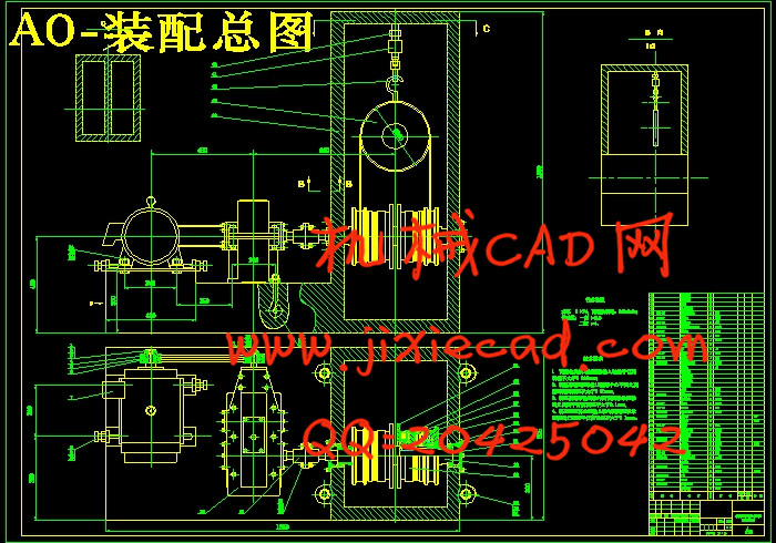
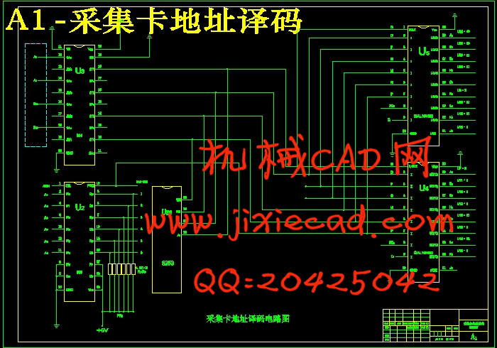
随着我国经济的快速发展,城市发展的步伐也进一步加快,高楼大厦层出不穷,而由此带来的安全隐患也在增大。救生缓降器正是基于减小人们的生命危险,保障人们的生命安全而产生的。它是一种简单、安全且实用的高楼逃生装置,在火灾发生时人们可使用它迅速脱离危险。本课题主要测定缓降器的安全及稳定性能。它由电动机、减速器、联轴器、电磁离合器、拉力传感器、测速发电机、直流调速器等部分组成。电机通过V带带动减速器,将速度减小到电磁离合器所需值。减速器通过联轴器与电磁离合器相联,将动力传到电磁离合器。电磁离合器上绕有缓降绳,缓降绳向上与缓降盘联结。缓降盘上接拉力传感器,通过拉力传感器测定绕过缓降盘的绳的拉力,拉力传感器与数据采集系统相接,将测得的拉力变化通过数据采集系统转换为数字量变化,在微机系统上显示出来。在电动机上接有测速发电机,测定电动机转速的变化,进而求得缓降绳下降速度的变化。当拉力在额定值内变化的时候,缓降绳下降速度也在额定值内变化,则缓降器符合设计要求,可作为逃生装置安装在楼道内。
关键词: 电动机; 减速器; 电磁离合器; 拉力传感器; 采集卡
英文摘要
Title The Experiment machine of Descent Rescue Device’s
Performance
Abstract
With the rapidly development of the economy of our country, the development steps of cities are speed upper and upper. Tall buildings emerges one after another incessantly, security hidden danger increases because of this. The Descent Rescue Device appears based on how to reduce people's life danger and how to Safeguards people's life. It is a simple, safely and practical escape device in tall buildings, and could enables people to escape dangers quickly when fire disaster occurs. In this topic, we mainly determine the safe and stable performance of the Descent Rescue Device. The Experiment machine of Descent Rescue Device’s Performance is makes up by electrical machinery, reduction gear, shaft coupling, magnetic clutch, pulling-force sensor, speed-survey generator and direct-current velometer, etc. The electrical machinery impetus the reduction gear through V-belt, and reduces the speed to the need value of the magnetic clutch. The reduction gear joins the magnetic clutch through the shaft coupling, and passes the power to the magnetic clutch. The Descent Rescue Device’s string circles on the magnetic clutch, and the Descent Rescue Device’s string joints upward with the Descent Rescue Device’s tray. The Descent Rescue Device’s tray joints with the pulling-force sensor, and determines the pulling force of the rope which round the Descent Rescue Device’s tray through the pulling-force sensor. The pulling-force sensor joint with the data acquisition system, and transforms the testing pulling force changes into the digital quantity changes through the data acquisition system, and demonstrates it on the microcomputer system. The speed-survey generator joint to the electrical machinery to determine the rotational speed changes of the electrical machinery and furthermore to determine the drop-speed changes of the Descent Rescue Device’s string. When the pulling force changes in the rated value time, the Descent Rescue Device’s string rate of descent also changes in the rated value, then the Descent Rescue Device conforms to the design requirement, and it could be installed in corridors as escaping device.
Keywords: electrical machinery; reduction gear; magnetic clutch; pulling-force sensor; gathering card
目 录
1 绪论……………………………………………………………………………1
2 总体方案设计…………………………………………………………………2
3 电动机的选择…………………………………………………………………4
3.1 电动机的选择………………………………………………………………4
3.2 分配传动比…………………………………………………………………5
3.3 传动装置动力与运动参数设计……………………………………………6
3.3.1 各轴转速………………………………………………………………6
3.3.2 各轴功率………………………………………………………………6
3.3.3 各轴转矩………………………………………………………………7
4 减速器设计……………………………………………………………………8
4.1 圆锥齿轮设计………………………………………………………………8
4.2 圆柱齿轮设计……………………………………………………………12
4.3 锥齿-圆柱齿轮设计数据小结……………………………………………17
4.3.1 锥齿轮数据…………………………………………………………17
4.3.2 圆柱齿轮数据………………………………………………………17
4.4 轴、轴承、键及联轴器型号的选择………………………………………18
4.4.1 Ⅰ-Ⅰ轴上轴径、轴承、键及油封的确定……………………………18
4.4.1.1 Ⅰ-Ⅰ轴上各轴段直径…………………………………………18
4.4.1.2 Ⅲ-Ⅳ及Ⅴ-Ⅵ轴段上轴承的确定……………………………18
4.4.1.3 Ⅰ-Ⅱ轴段及Ⅵ-Ⅶ轴段上键的确定…………………………19
4.4.1.4 Ⅱ-Ⅲ轴上油封的确定…………………………………………20
4.4.2 Ⅱ-Ⅱ轴上轴径、轴承、键的确定……………………………………20
4.4.3 Ⅲ-Ⅲ轴上轴径、轴承、键及联轴器的确定…………………………21
5 其它机械结构设计…………………………………………………………22
5.1 带传动设计………………………………………………………………22
5.1.1 带传动的类型………………………………………………………22
5.1.2 带传动的选择………………………………………………………22
5.1.3 V带轮设计……………………………………………………………22
5.2 联轴器的设计……………………………………………………………23
5.2.1 联轴器的分类………………………………………………………23
5.2.2 联轴器的选择………………………………………………………24
5.3 电磁离合器的选择………………………………………………………24
5.3.1 电磁离合器的特点…………………………………………………24
5.3.2 电磁离合器的分类…………………………………………………25
5.3.3 各种电磁离合器的使用范围………………………………………26
5.3.4 电磁离合器在机械传动装置上的应用形式………………………28
5.3.5 电磁离合器的选择…………………………………………………30
5.4 传感器的选择……………………………………………………………31
5.4.1 传感器的分类………………………………………………………31
5.4.2 传感器的选择………………………………………………………31
6 数据采集与处理……………………………………………………………32
6.1 数据采集原理……………………………………………………………32
6.2 数据采集系统……………………………………………………………33
6.2.1 数据采集系统的基本组成…………………………………………33
6.2.2 数据采集系统的特点………………………………………………34
6.2.3 数据采集系统的主要性能指标……………………………………35
6.2.4 数据采集系统的结构形式…………………………………………36
6.3 程序控制设计……………………………………………………………37
6.4 转速测量…………………………………………………………………40
6.4.1 直流测速发电机……………………………………………………41
6.4.2 交流测速发电机……………………………………………………42
6.4.3 测速发电机的选择…………………………………………………43
结论………………………………………………………………………………44
致谢………………………………………………………………………………45
参考文献…………………………………………………………………………46


