设计简介
摘要
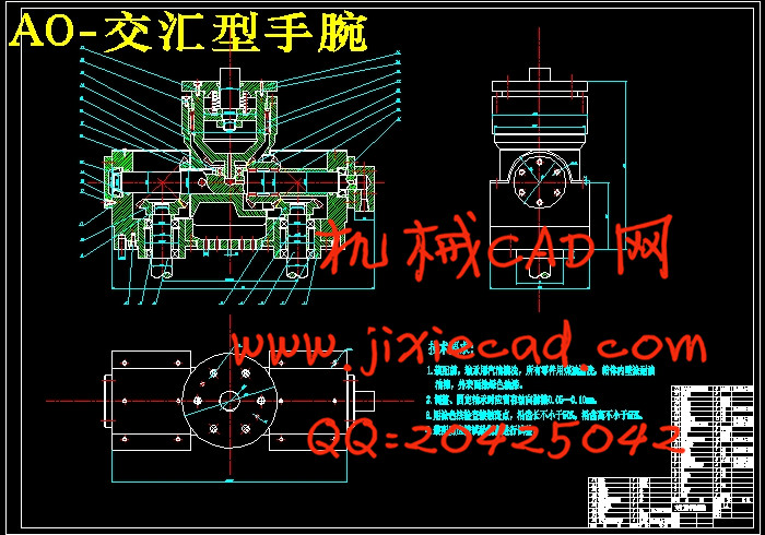
在工业上,机器人有着广泛的应用,尤其是在高温,高压,粉尘,噪音,以及带有放射性和污染的场合。而工业机器人是相对较新的电子设备,它正开始改变现代化工业面貌。手腕是连接末端执行器和手臂的关键,是联接手部与臂部的部件,它的作用是调整或改变工件的方位。本设计为三自由度工业机器人手腕,可以在两个方向上旋转在一个方向上弯转的汇交型腕部设计。在设计过程中使用了大量的标准零件以降低成本但是由于大量采用标准零件,使机器人手腕内部剩余空间比较大,如果加入部分非标准零件的话就可以节约部分空间,使结构更加的紧凑,但是相应的成本也会随之提高。
汇交型腕部的结构用CAD软件完成从建模到运动学分析。三维造型采用的造型软件为SOLIDWORKS, SOLIDWORKS以其易学易用、功能强大和互连互通的特点,推动了整个产品开发机构中个人效率和过程效率的提高。它既能节省时间和成本,又能提高产品质量。由于零件图是分开绘制,在装配过程中可能产生部分结构与设计不符的情况。如果采用整体设计的思路的话将可以使本设计的参数可调性有比较大的提高。本文的主要内容:
(1)确定三自由度腕部的传动方案及传动系统设计;
(2)回转力矩计算及其他相关计算;
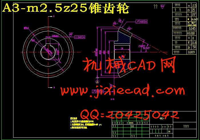
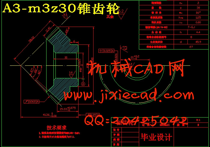
(3)零件设计与校核。轴承校核:设计中所用的所有重要轴承都要经过强度校核。在满足尺寸和强度要求的情况下,尽可能地选用国产轴承,以降低机器人的成本。轴的校核:设计中所用的所有较重要的轴都要经过强度校核和刚度校核。齿轮选用:设计中所用的所有齿轮都要经过强度校核。键及花键:设计中所用的所有较重要的键及花键都要经过强度校核。销与螺钉:设计中所用的所有较重要的销与螺钉都要经过强度校核。
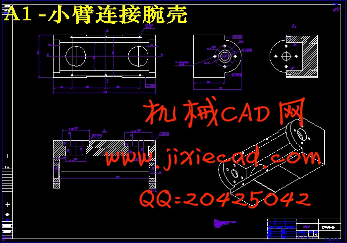
(4)零件图的绘制与三维模型建立;
(5)绘制装配图及运动仿真。
关键词:机器人 汇交型 腕部设计 SOLIDWORKS 运动仿真
Abstract
Has been widely used in industry, robot, especially at high temperature, high pressure, dust, noise, and radioactive pollution occasion. Industrial robots are relatively new electronic devices, it is beginning to change the appearance of modern industry. Wrist is the key to the connection terminal actuator and arm, is to join hand and arm parts, its role is to adjust or change the orientation of the workpiece. This design for three degrees of freedom industrial robot wrist, can rotate in one direction in two directions on the ways of concurrent wrist type design. In use a lot of standard parts in the design process in order to reduce cost but due to the use of standard parts, makes the robot wrist to the remaining space is larger, if add some non-standard parts can save some space, make the structure more compact, but the cost will increase accordingly.
Concurrent type structure of the wrist finish from modeling to kinematics analysis with CAD software. 3 d modelling using modeling software SOLIDWORKS, SOLIDWORKS with its easy to learn easy to use, powerful functions and the characteristics of interconnection and interflow, promoted the individual efficiency throughout the product development organization and the improvement of process efficiency. It can save time and cost, and can improve the quality of products. Because the parts are separate mapping, part of the structure may be produced during the process of assembly does not accord with design. If adopt the overall design train of thought will be able to make this design parameter adjustable there is a big improvement. The main content of this article:
(1) to determine the three degrees of freedom the wrist transmission scheme and system design;
(2) torque calculation and other related calculation;
(3) the component design and checking. Bearing checking: used in the design of all the important bearing through the strength check. In circumstances that could satisfy the requirement of size and strength, as far as possible choose domestic bearing, in order to reduce the cost of the robot. Check shaft: used in the design of all the more important are through intensity and rigidity of the shaft. All gear used in the design of gear selection: go through strength check. Button and spline is used in the design of all keys and spline is more important to after stress test. Used in the design of pin and screw: all the more important pin and screw through the strength check.
(4) parts figure drawing and 3 d model;
(5) drawing assembly and motion simulation.
Keywords: concurrent type robot wrist design SOLIDWORKS motion simulation
目录
摘要 4
Abstract 5
第一章 绪论 6
1.1 引言 6
1.2机器人组成 8
1.3机器人分类 9
1.3.1按用途分类 9
1.3.2按控制形式分类 10
1.3.3按驱动方式分类 10
1.4 腕部结构选型 10
1.4.1单自由度手腕 12
1.4.2两自由度手腕 12
1.4.3三自由度手腕 13
1.4.4 通用机器人腕部结构选型 14
1.5 本文主要内容 15
第二章 汇交型腕部设计方案 17
2.1 腕部的结构特点 17
2.1.1 概述 17
2.1.2单自由度手腕 17
2.1.3二自由度手腕 18
2.1.4三自由度手腕 18
2.1.5柔顺手腕结构 19
2.2 腕部的驱动机构 19
2.3 手腕结构的选择 20
2.4 传动装置的运动和动力参数计算 22
2.4.1.选择电机 22
2.5 传动装置的运动和动力参数 25
2.5.1 各轴的转速 25
第三章 汇交型腕部相关零件计算及校核 27
3.1 锥齿轮2,8的设计计算 27
4.1.1 选材料并确定初步参数 27
4.1.2 齿面接触疲劳强度计算 27
4.1.3 齿根抗弯疲劳强度验算 28
4.1.4 主要几何尺寸计算 29
3.2锥齿轮4,6的设计 30
4.2.1选材料并确定初步参数 30
4.2.2 齿面接触疲劳强度计算 30
4.2.3 齿根抗弯疲劳强度验算 31
4.2.4 主要几何尺寸计算 32
3.3轴的选用与校核 33
3.4滚动轴承 38
3.5键连接 41
3.6销联接 42
3.7螺纹联接 42
第四章 汇交型腕部三维建模及仿真 44
4.1 造型软件简介 44
4.2交汇型腕部结构建模 46
4.3交汇型腕部结构运动仿真分析 50
总结 53
致谢 54
参考文献 55


