设计简介
轿车变速箱的设计
摘要
据中国汽车工业协会统计分析,2013年,汽车产销双超2000万辆,增速大幅提升,高于年初预计,并且再次刷新全球纪录,目前为止,已连续五年蝉联全球第一。
汽车变速箱作为汽车传动系统重要组成部分,随着计算机科学技术的发展,它历经了手动变速、自动变速、自动/手动变速时代。
本设计的任务是关于前置后驱(Front engine Rear wheel drive, 简称FR)式小轿车用手动变速箱的设计。FR在轴荷分配上,可以达到50:50的最佳比例,因此它具有较好的操控性、稳定性、动力性和制动性等优点。这也是高性能汽车设计至今依然喜欢采用FR的主要原因。三轴式变速箱具有体积小、原理简单、工作可靠和操纵方便等优点,故在大多数汽车中得到应用。
本文是在认真了解和学习了汽车相关理论和设计知识的基础上,首先确定FR轿车手动变速箱的设计方案,包括变速箱传动机构布置、主要参数的选择、设计与计算、同步器设计、操纵机构、结构元件等;其次,根据所给定参数和条件,完成齿轮、轴和轴承等主要零件的理论分析,结合CAD中的AutoCAD、Pro/E、SolidWorks、UG和CAE中的ANSYS软件,对所建立的三维模型进行动力学与有限元分析,继而优化,将优化后的模型再进行模拟仿真得到优化后结果。
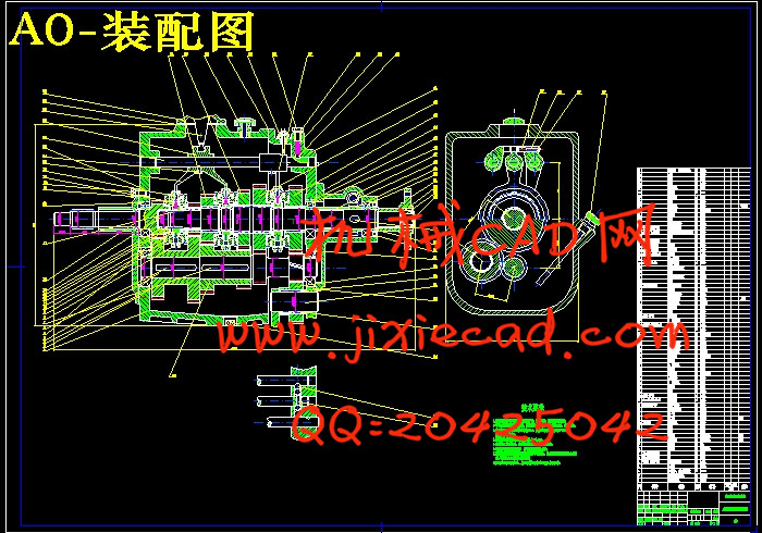
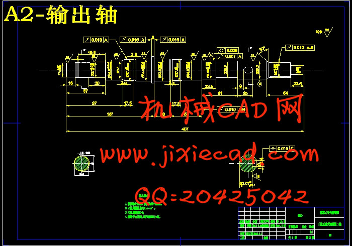
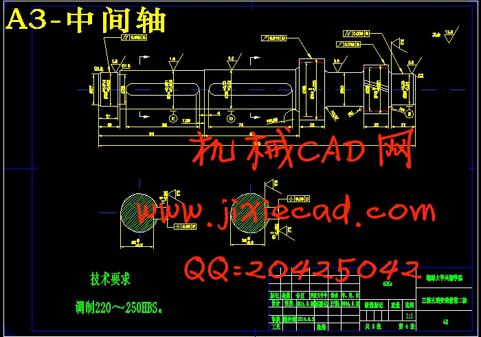
三轴式五速变速箱包括五个前进挡和一个倒挡,并通过锁环式同步器来实现换挡。它有3根主要的传动轴:第一轴(输入轴)、第二轴(输出轴)、中间轴(主动轴),所以称三轴式变速箱,另外还有倒挡轴。它的功用是:1.改变传动比,在较大范围内改变汽车的行驶速度和汽车驱动轮上转矩的数值,以适应经常变化的行驶条件,同时使发动机在有利的(功率较高而油耗率较低)工况下工作;2.在发动机旋转方向不变的前提下,利用倒挡实现汽车倒向行驶;3.在发动机不熄火的情况下,利用空挡中断动力传递,可以使驾驶员松开离合器踏板离开驾驶位置,且便于汽车启动、怠速、换挡和动力输出。
关键词:变速箱,传动比,中间轴,第二轴,齿轮,锁环式同步器
THE DESIGN OF SALOON GEARBOX
ABSTRACT
According to China Association of Automobile Manufacturers, the number of automobiles sales has rapidly increased to 20 million, which is higher than that estimated at the start of the year. The result has set a new record again, and won five consecutive first.
With the development of computers, auto gearbox, as an important part of automotive transmission system, has experienced three periods: manual transmission, automatic transmission, and automatic / manual transmission.
The paper is aimed at the manual gearbox design of the cars with Front engine Rear wheel drive(FR).On the axle load distribution, FR can reach the optimum ratio of 50:50,for it has extraordinary handling, stability and braking power. Therefore, high-performance cars prefer to use FR. Besides, three-shaft gearbox is widely used in most cars due to its small size, simple principle, reliability and easy operation.
The paper is based on a good learning of automotive-related theories and design knowledge. Firstly, I make an FR car manual gearbox design including gearbox transmission layout, choice of the main parameters and calculation, synchronous design, operation mechanism, structural elements, etc. Secondly, according to the parameters and requirements, I have worked out the theoretical analysis about gears, shafts and bearings and other major parts. With CAD in AutoCAD, Pro / E, SolidWorks, UG and ANSYS software in CAE, I analyze the three-dimensional model of established dynamics and finite elements and the model is optimized further to get the simulation results.
Three five-speed gearbox shaft includes five forward gears and one reverse gear. It shifts by locking ring synchronizer. It has three main transmission shafts. It is called three-shaft gearbox, owing to the three shafts---the first shaft (input shaft), the second shaft (output shaft) and intermediate shaft (drive shaft). Besides, it has reverse gear shaft. Firstly, it can adjust the transmission ratio to change the speed of the drive wheels and the torque value in a wide range to adapt to frequent changes in driving conditions, in order that the vehicle can work in an advantageous condition where there is higher power and lower fuel consumption rate. Secondly, under the premise of engineer rotation without changing, it’s a good idea to use reverse gear to achieve backward driving car. Thirdly, in case the engine does not stall, neutral gear can interrupt power transmission, allowing the driver to release the clutch pedal to leave the driving position and it’s easy to start, idle, shift and output power.
Key words: transmission, transmission ration, intermediate shaft, second shaft, gear, locking ring synchronizer
目 录
摘要 1
符号表 4
第一章 绪论 6
1.1 变速箱的工作原理 6
1.2 变速箱的功用和要求 7
1.3 变速箱的分类 7
1.3.1 手动变速箱(MT) 8
1.3.2 自动变速箱(AT) 8
1.3.3 手动自动变速箱(AMT) 8
1.3.4 无级变速箱(CVT) 9
1.3.5 其它分类方法 9
1.4 汽车变速箱的发展现状及其技术趋势 10
1.5 了解、认知手动变速箱的必要性 11
第二章 变速箱传动机构布置方案的确定 12
2.1 传动机构布置方案分析 12
2.1.1 固定轴式变速箱 13
2.1.2 倒挡方案布置方案 16
2.2 部件结构方案分析 17
2.2.1 齿轮型式 18
2.2.2 换挡机构型式 18
2.2.3 自动脱挡 18
2.2.4 变速箱轴承 20
第三章 变速箱主要参数的选择 22
3.1 挡数 22
3.2 传动比范围 22
3.3 中心距A 22
3.4 外形尺寸 23
3.5 齿轮参数 23
3.5.1 模数 23
3.5.2 齿形、压力角α、螺旋角β和齿宽b 24
3.5.3 齿轮变位系数的选择 25
3.5.4 齿顶高系数 25
3.6 各挡齿轮齿数的分配 25
3.6.1 确定一挡齿轮的齿数 26
3.6.2 确定常啮合齿轮副的齿数 26
3.6.3 确定其他挡位的齿数 27
3.6.4 确定倒挡齿轮的齿数 27
第四章 变速箱齿轮的强度计算和材料选择 29
4.1 齿轮的损坏形式 29
4.2 轮齿强度计算 29
4.2.1 轮齿弯曲强度计算 29
4.2.2 齿轮接触应力 31
第五章 变速箱轴的强度计算与校核 33
5.1 变速箱轴的结构和尺寸 33
5.1.1 轴的结构 33
5.1.2 确定轴的尺寸 33
5.1.3 初选轴的直径 34
5.2 轴的强度验算 34
5.2.1 第一轴的强度与刚度校核 34
5.2.2 第二轴的校核计算 35
第六章 变速箱同步器的设计 37
6.1 同步器的结构 37
6.2 同步环主要参数的确定 38
6.2.1 同步环锥面上的螺纹槽 38
6.2.2 锥面半锥角 39
39
6.2.3 摩擦锥面平均半径R 39
6.2.4 锥面工作长度b 39
6.2.5 同步环径向厚度 39
6.2.6 锁止角β 39
6.2.7 同步时间t 40
第七章 变速箱的操纵机构 41
7.1 操纵式 41
7.1.1 直接操纵式 41
7.1.2 远距离操纵式 41
7.2 换挡锁装置 41
7.2.2 互锁装置 42
7.2.3 倒挡锁装置 42
参考文献 44
结论 46
致谢 47
Appendix 48
摘要
据中国汽车工业协会统计分析,2013年,汽车产销双超2000万辆,增速大幅提升,高于年初预计,并且再次刷新全球纪录,目前为止,已连续五年蝉联全球第一。
汽车变速箱作为汽车传动系统重要组成部分,随着计算机科学技术的发展,它历经了手动变速、自动变速、自动/手动变速时代。
本设计的任务是关于前置后驱(Front engine Rear wheel drive, 简称FR)式小轿车用手动变速箱的设计。FR在轴荷分配上,可以达到50:50的最佳比例,因此它具有较好的操控性、稳定性、动力性和制动性等优点。这也是高性能汽车设计至今依然喜欢采用FR的主要原因。三轴式变速箱具有体积小、原理简单、工作可靠和操纵方便等优点,故在大多数汽车中得到应用。
本文是在认真了解和学习了汽车相关理论和设计知识的基础上,首先确定FR轿车手动变速箱的设计方案,包括变速箱传动机构布置、主要参数的选择、设计与计算、同步器设计、操纵机构、结构元件等;其次,根据所给定参数和条件,完成齿轮、轴和轴承等主要零件的理论分析,结合CAD中的AutoCAD、Pro/E、SolidWorks、UG和CAE中的ANSYS软件,对所建立的三维模型进行动力学与有限元分析,继而优化,将优化后的模型再进行模拟仿真得到优化后结果。
三轴式五速变速箱包括五个前进挡和一个倒挡,并通过锁环式同步器来实现换挡。它有3根主要的传动轴:第一轴(输入轴)、第二轴(输出轴)、中间轴(主动轴),所以称三轴式变速箱,另外还有倒挡轴。它的功用是:1.改变传动比,在较大范围内改变汽车的行驶速度和汽车驱动轮上转矩的数值,以适应经常变化的行驶条件,同时使发动机在有利的(功率较高而油耗率较低)工况下工作;2.在发动机旋转方向不变的前提下,利用倒挡实现汽车倒向行驶;3.在发动机不熄火的情况下,利用空挡中断动力传递,可以使驾驶员松开离合器踏板离开驾驶位置,且便于汽车启动、怠速、换挡和动力输出。
关键词:变速箱,传动比,中间轴,第二轴,齿轮,锁环式同步器
THE DESIGN OF SALOON GEARBOX
ABSTRACT
According to China Association of Automobile Manufacturers, the number of automobiles sales has rapidly increased to 20 million, which is higher than that estimated at the start of the year. The result has set a new record again, and won five consecutive first.
With the development of computers, auto gearbox, as an important part of automotive transmission system, has experienced three periods: manual transmission, automatic transmission, and automatic / manual transmission.
The paper is aimed at the manual gearbox design of the cars with Front engine Rear wheel drive(FR).On the axle load distribution, FR can reach the optimum ratio of 50:50,for it has extraordinary handling, stability and braking power. Therefore, high-performance cars prefer to use FR. Besides, three-shaft gearbox is widely used in most cars due to its small size, simple principle, reliability and easy operation.
The paper is based on a good learning of automotive-related theories and design knowledge. Firstly, I make an FR car manual gearbox design including gearbox transmission layout, choice of the main parameters and calculation, synchronous design, operation mechanism, structural elements, etc. Secondly, according to the parameters and requirements, I have worked out the theoretical analysis about gears, shafts and bearings and other major parts. With CAD in AutoCAD, Pro / E, SolidWorks, UG and ANSYS software in CAE, I analyze the three-dimensional model of established dynamics and finite elements and the model is optimized further to get the simulation results.
Three five-speed gearbox shaft includes five forward gears and one reverse gear. It shifts by locking ring synchronizer. It has three main transmission shafts. It is called three-shaft gearbox, owing to the three shafts---the first shaft (input shaft), the second shaft (output shaft) and intermediate shaft (drive shaft). Besides, it has reverse gear shaft. Firstly, it can adjust the transmission ratio to change the speed of the drive wheels and the torque value in a wide range to adapt to frequent changes in driving conditions, in order that the vehicle can work in an advantageous condition where there is higher power and lower fuel consumption rate. Secondly, under the premise of engineer rotation without changing, it’s a good idea to use reverse gear to achieve backward driving car. Thirdly, in case the engine does not stall, neutral gear can interrupt power transmission, allowing the driver to release the clutch pedal to leave the driving position and it’s easy to start, idle, shift and output power.
Key words: transmission, transmission ration, intermediate shaft, second shaft, gear, locking ring synchronizer
目 录
摘要 1
符号表 4
第一章 绪论 6
1.1 变速箱的工作原理 6
1.2 变速箱的功用和要求 7
1.3 变速箱的分类 7
1.3.1 手动变速箱(MT) 8
1.3.2 自动变速箱(AT) 8
1.3.3 手动自动变速箱(AMT) 8
1.3.4 无级变速箱(CVT) 9
1.3.5 其它分类方法 9
1.4 汽车变速箱的发展现状及其技术趋势 10
1.5 了解、认知手动变速箱的必要性 11
第二章 变速箱传动机构布置方案的确定 12
2.1 传动机构布置方案分析 12
2.1.1 固定轴式变速箱 13
2.1.2 倒挡方案布置方案 16
2.2 部件结构方案分析 17
2.2.1 齿轮型式 18
2.2.2 换挡机构型式 18
2.2.3 自动脱挡 18
2.2.4 变速箱轴承 20
第三章 变速箱主要参数的选择 22
3.1 挡数 22
3.2 传动比范围 22
3.3 中心距A 22
3.4 外形尺寸 23
3.5 齿轮参数 23
3.5.1 模数 23
3.5.2 齿形、压力角α、螺旋角β和齿宽b 24
3.5.3 齿轮变位系数的选择 25
3.5.4 齿顶高系数 25
3.6 各挡齿轮齿数的分配 25
3.6.1 确定一挡齿轮的齿数 26
3.6.2 确定常啮合齿轮副的齿数 26
3.6.3 确定其他挡位的齿数 27
3.6.4 确定倒挡齿轮的齿数 27
第四章 变速箱齿轮的强度计算和材料选择 29
4.1 齿轮的损坏形式 29
4.2 轮齿强度计算 29
4.2.1 轮齿弯曲强度计算 29
4.2.2 齿轮接触应力 31
第五章 变速箱轴的强度计算与校核 33
5.1 变速箱轴的结构和尺寸 33
5.1.1 轴的结构 33
5.1.2 确定轴的尺寸 33
5.1.3 初选轴的直径 34
5.2 轴的强度验算 34
5.2.1 第一轴的强度与刚度校核 34
5.2.2 第二轴的校核计算 35
第六章 变速箱同步器的设计 37
6.1 同步器的结构 37
6.2 同步环主要参数的确定 38
6.2.1 同步环锥面上的螺纹槽 38
6.2.2 锥面半锥角
6.2.3 摩擦锥面平均半径R 39
6.2.4 锥面工作长度b 39
6.2.5 同步环径向厚度 39
6.2.6 锁止角β 39
6.2.7 同步时间t 40
第七章 变速箱的操纵机构 41
7.1 操纵式 41
7.1.1 直接操纵式 41
7.1.2 远距离操纵式 41
7.2 换挡锁装置 41
7.2.2 互锁装置 42
7.2.3 倒挡锁装置 42
参考文献 44
结论 46
致谢 47
Appendix 48


