设计简介
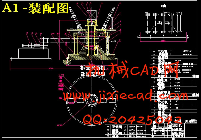
摘要:随科技的进步,世界各国对导弹的机动性能要求越来越高,但导弹在过载飞行过程中的受力比较复杂,为保证导弹产品的质量和可靠性,不会在机动过载飞行中失效,因而需要一种地面模拟装置,模拟导弹发动机飞行的过载。所以设计了发动机过载模拟实验台。
发动机过载模拟实验台是通过传动系统使固定在旋转架上的发动机转动而产生离心力,在过载情况下测试其某些性能参数的变化情况的机器。通过离心机可以实现发动机内的弹道参数、离轴加速度、壳体应变以及温度等的测量。
根据上述思想和原理,围绕方案的可行性、工艺制造的简捷性以及尽可能的低成本方面考虑,最后得出现行方案。本设计已通过生产部门确认,为此后的制造加工奠定了基础。
关键词:发动机 实验 旋转 离心加速度 设计
Abstract: With the advancements of technology, the world of the missile’ s maneuverability increasingly high demand. However, the missiles are flying off course by the relatively complex. Missile products to ensure the quality and reliability, tactical not overload failure in flight, As a result, Need a kind of ground to imitate the device which imitate the guided missile to launch the machine flight of over carry。Therefore, The overload simulation laboratory bench of the engine has been designed.
The overload simulation laboratory bench of the engine is through the transmission system make the engine which install at the rotators shelf to rotate, that make the engine has the centrifugal force, tests its certain performance parameter change in the overload situation. pass left scheming can realize launch machine and leave the stalk acceleration, hull adapts to changes and the diagraph that temperature wait.
According to the above thought and the principle, revolve the plan of feasibility, craft manufacture simple and as far as possible low cost aspect considered, finally obtains the present plan. This design confirmed through the production department, and for hereafter the manufacture processing has laid the foundation.
Key words: The engine Experiment Revolves
The centrifugal acceleration Design
目录
一 前 言
1.1 选题的意义 1
1.2 国内外发展状况 2
1.3 论文的主要内容 3
1.4本设计的特点: 4
二 实验台的方案设计与选择
2.1原始数据及技术要求 5
2.1.1 待测发动机数据 5
2.1.2 实验台技术参数 5
2.1.3 转台运动控制 5
2.2 总体方案的设计 5
2.2.1 方案1 5
2.2.2 方案2 7
2.2.3 方案3 8
2.3方案选择 10
2.3.1方案的特点 10
2.3.2 各方案之间的比较与选择 12
三 设计计算和校核
3.1电动机的选择: 13
3.1.1选择电动机类型和结构型式 13
3.1.2 选择电动机的容量 13
3.1.3确定电动机转速 14
3.1.4 电动机的安装 15
3.2 V带的选择与计算 16
3.2.1传动方式的比较和选用 16
3.2.2 计算 16
3.3V带轮的设计 19
3.3.1V带轮设计的要求 19
3.3.2带轮的材料 20
3.3.3结构尺寸 20
3.3.4V带轮的形状和尺寸设计 20
3.4联轴器的选择和校核 21
3.4.1用途 21
3.4.2 特点与选择 21
3.4.3校核 22
3.5轴承的选择 22
3.5.1概述: 22
3.5.2特点与选择 22
3.6键的选择和校核 23
3.6.1概述 23
3.6.2旋转平台与被动带轮的键的选择和校核 24
3.7 旋转平台的设计与校核 24
3.7.1 概述: 24
3.7.2旋转平台的设计与校核计算 25
四 零部件的外形结构设计
4.1总体装配图 31
4.1.1图形 31
4.1.2基本数据 31
4.2 支撑定架 32
4.2.1图形 32
4.2.2基本数据 32
4.3定轴 33
4.3.1图形 33
4.3.2 基本数据: 33
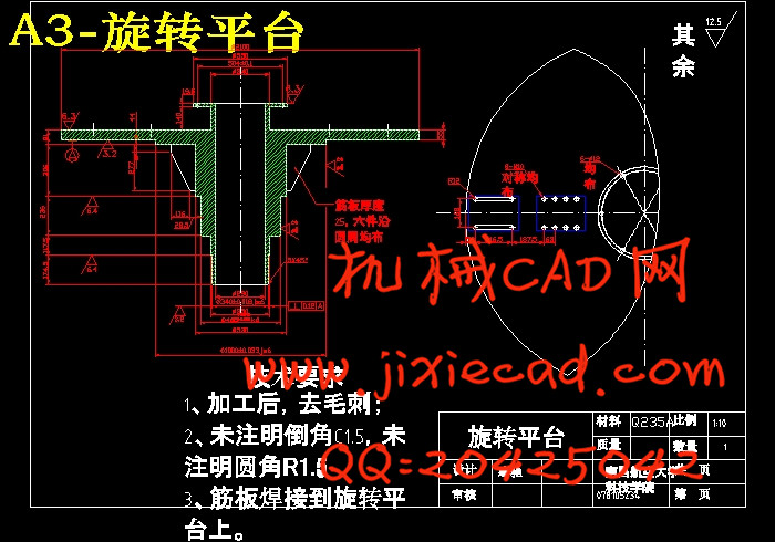
4.4 旋转平台: 34
4.4.1 图形 34
4.4.2 基本数据: 34
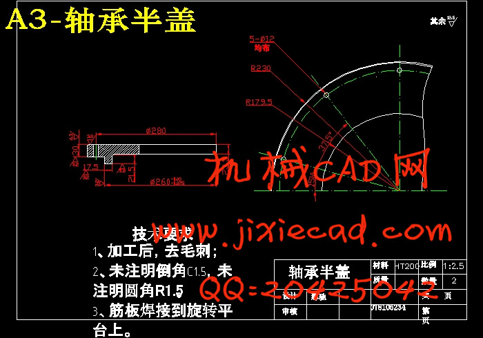
4.5 轴承半盖: 35
4.5.1 图形: 35
4.5.2 基本数据: 35
4.6 集流环套: 36
4.6.1 图形: 36
4.6.2 基本数据: 36
4.7 集流环接头: 37
4.7.1 图形: 37
4.7.2 基本数据: 37
4.8 安装圆板: 38
4.8.1 图形: 38
4.8.2 基本数据: 38
五 润滑方式的对比及选择
5.1润滑油和润滑脂的比较 39
5.2 润滑剂的选择 39
六 夹紧方案的设计与选择
6.1工件的夹紧的要求 40
6.2 方案的比较 40
6.2.1 方案1 40
6.2.2方案2 41
6.2.3两种方案的比较 42
小结 43
致谢 44
参考文献 45
外文翻译 46


