设计简介
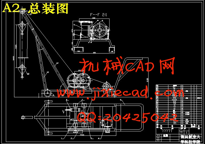
摘要:本课题的目的就是设计一简易吊车来代替人力实现重物的搬运。该吊车的工作原理是:由电动机经带轮传动和一对开式齿轮传动,将运动和动力传给卷筒,再通过钢丝绳和滑轮组来提升重物。
首先 经过全面分析确定了传动方案。通过设计计算所得到的相关参数,直接就确定了一些标准零部件,这其中就包括了钢丝绳,电动机,轴承,键等,并确定了总体结构方案。
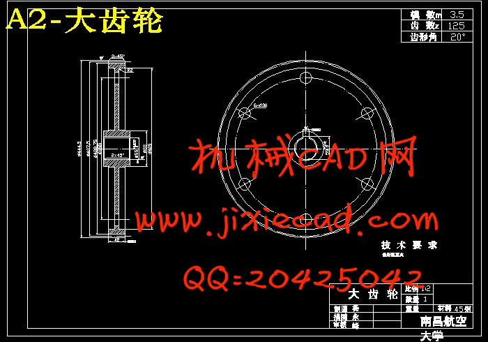
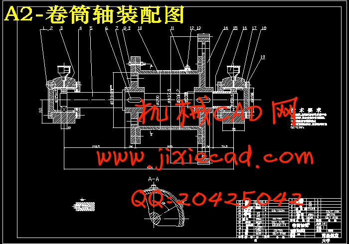
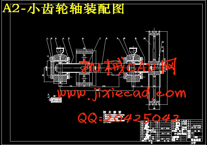
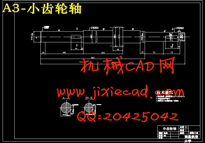
本文的设计包括卷筒和滑轮等。在传动装置的设计和计算中有制动器的选择,通过选择制动器也就确定了传动方案。在结构设计中,包括轴的设计、确定了带轮的结构、齿轮的结构、卷筒的结构、滑轮的结构。最后通过设计计算还确定了伸臂杆和支撑杆的尺寸及。
关键词:简易吊车 设计计算 结构设计
Abstract: The purpose of this issue is a simple design of the cable car to replace the realization of human handling of heavy objects. The cable car's working principle is: the motor pulley and a drive off-gear transmission, movement and power transmission reel, and then through the rope and pulley group to raise heavy objects.
After the first comprehensive analysis of the transmission programme. Through the design calculated by the relevant parameters, directly identified a number of standard components, which included rope, motors, bearings, keys, etc., and to determine the overall structure of the programme.
In this paper, including the design of drum and pulley, and so on. In the transmission of the design and calculation of a brake choice, by selecting the brakes will determine the transmission programme. In structural design, including the shaft design, determine the structure of the pulley, gear structure, roll the structure, the structure of the pulley. Finally, design and calculation also identified Shenbi-and supporting bar and the size.
Keyword: Simple cable car Calculation Structural Design
目 录
1 绪论 ………………………………………………………………………(1)
1.1 吊车的历史 ……………………………………………………………… (1)
1.2 吊车国内外的研究现状 ………………………………………………… (1)
1.3 吊车的发展趋势 ………………………………………………………(2)
2 工作机构的设计…………………………………………………………(4)
2.1 钢丝绳的选择 ……………………………………………………………(4)
2.1.1 钢丝绳的种类 …………………………………………………………(4)
2.1.2 钢丝绳的型号…………………………………………………………(4)
2.1.3 钢丝绳直径的选择……………………………………………………(5)
2.2 卷筒和滑轮直径的选择 …………………………………………………(5)
3 传动装置的设计和计算……………………………………………… (7)
3.1 计算卷筒的功率 ………………………………………………………… (7)
3.2 计算卷筒的转速 ………………………………………………………… (7)
3.3 电动机的选择 …………………………………………………………… (7)
3.3.1 电动机类型的选择 ………………………………………………… (7)
3.3.2 电动机转速的选择 ………………………………………………… (8)
3.3.3 电动机功率的选择 ………………………………………………… (8)
3.4 计算总传动比…………………………………………………………… (8)
3.5 确定传动方案,画出传动示意图……………………………………… (9)
3.6 分配传动比……………………………………………………………… (9)
3.7 计算效率。验算电动机的功率…………………………………………(10)
3.8 计算各轴的转速、功率和转矩…………………………………………(10)
3.9 制动器的选择……………………………………………………………(12)
3.10 传动机构的设计和计算 ……………………………………………… (13)
3.10.1 带传动 ……………………………………………………………… (13)
3.10.2 齿轮传动 …………………………………………………………… (15)
3.11 画出总体结构方案图 ………………………………………………… (16)
4 结构设计 ……………………………………………………………… (17)
4.1 初算各轴的最小直径……………………………………………………(17)
4.2 带轮的结构………………………………………………………………(18)
4.3 齿轮的结构………………………………………………………………(19)
4.4 卷筒的结构………………………………………………………………(20)
4.5 滑轮的结构………………………………………………………………(21)
4.6 升臂杆和支撑杆的结构…………………………………………………(21)
4.6.1 升臂杆和支撑杆的尺寸………………………………………………(21)
4.6.2 根据强度条件、决定升臂杆的材料和断面尺寸……………………(22)
4.6.3 根据强度条件,决定支撑杆的材料和断面尺寸……………………(25)
4.7 画制动轮装置和卷同装置的结构图 ……………………………………(26)
4.8 绘制吊车的总装配图 ……………………………………………………(26)
4.9 拆画重要零件图 …………………………………………………………(26)
5 设计小结 …………………………………………………………………(27)
5.1 小结 ………………………………………………………………………(27)
5.2 设计心得 …………………………………………………………………(27)
参考文献………………………………………………………………………(29)
致 谢……………………………………………………………………………(30)


