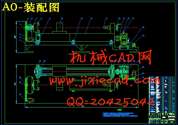
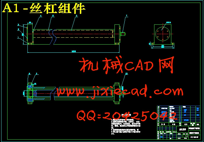
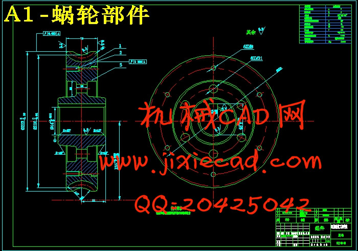
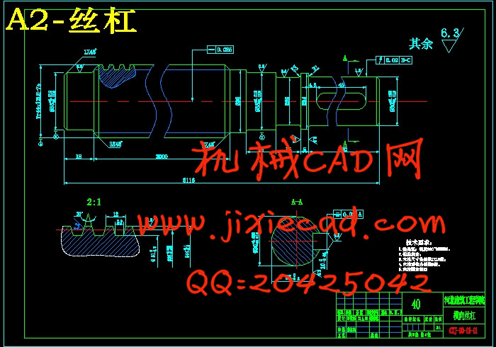
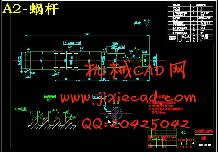
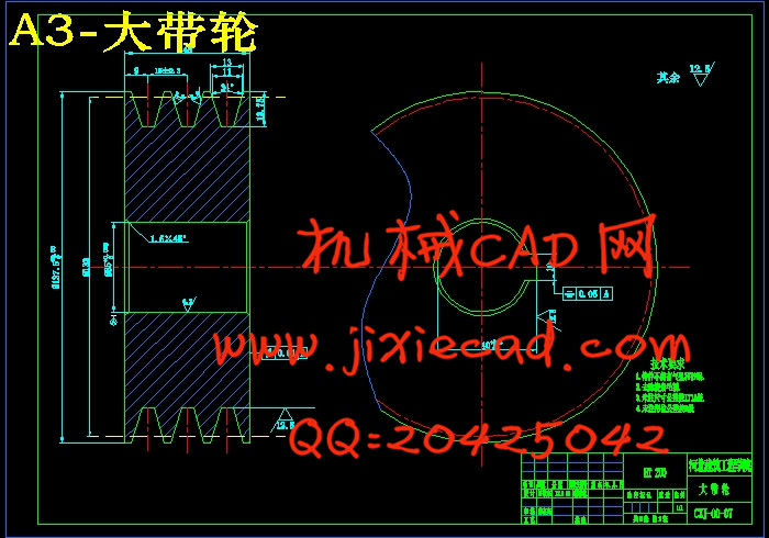
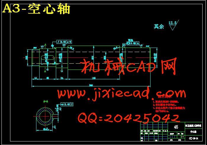
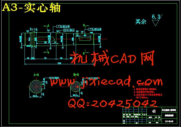
设计简介
摘 要
这篇设计主要阐述的是管道除锈机的设计,管子除锈是管子使用前的一项重要工序,尤其是在钢管使用后非常有必要对管道进行除锈。这对钢管的使用寿命有着很重要的意义。
本设计方案是:该机主要由机架、电动机、变速传动机构、主轴、钢丝刷、圆盘机构等组成。除锈由电机带动,通过普通圆柱蜗轮蜗杆减速器来减速。蜗杆传动是用来传递空间互相垂直的两项错轴之间的运动和动力的一种机械传动形式。由于蜗轮蜗杆传动可以实现自锁,传动比大,噪音小的原因,所以选择蜗轮蜗杆传动。
现有的除锈机,其体积大,不宜搬动,而且把管道固定在机床上后,需要人力用砂纸打磨,一般总共需要3-4个人来工作。耗费人力不说,并且工作环境非常恶劣。
本设计是在机械动力头的基础上,增加适当的零件,实现金属管子机械化除锈工作,达到成本较低、结构合理、劳动强度低、效率高的目的。
本设计需要明确设计任务,由相关的任务书和工具书确定设计的传动方案为机械传动。由以知条件,可计算出工作力和工作速度。选电机,拟定两级减速的各个传动比,确定各级减速的输入输出功率、转速、转矩。其次,查找主要技术参数,明确设计原则,由相关的公式进行轴及各类零件的强度,稳定性及寿命的校核计算;进行机架的设计,包括床身,加紧装置形式的明确和对其强度,刚度,稳定性的校核计算。最后,全面分析设计结果是否符合设计要求,完善各个细节。
关键词:除锈机 普通圆柱蜗轮蜗杆减速器 圆柱齿轮减速器 夹紧机构 螺杆
Abstract
This graduation project is a pipeline of major rust on the machine design, the tube removing is an important process of the tube before using, especially in the steel pipe is used it is necessary to rust pipes. This pipe has a life of significance.
This designed plan is consisted mainly by the rack, electric motors, variable speed transmission, spindle, steel wire brush, disc component institutions. Rust by the motor driven by ordinary cylindrical worm gear reducer to slow down. Worm-drive space is used to pass each other the wrong vertical axis between the two campaigns and a dynamic form of mechanical transmission. As the worm drive can achieve self-locking, the transmission ratio, and noise reasons, so I chose to drive worm.
Removing the existing machine, its size should not be moving, and the pipe is fixed in the machine tool, the need for human polished with sandpaper, generally a total of 3-4 individuals to work. Labor-to say the least, and very bad work environment.
This design is the first in the mechanical power on the basis of the increase in the appropriate parts, the realization of mechanization rust metal pipe work, low cost, reasonable structure, low labor intensity, high efficiency purposes.
The design needs a clear designed mandate, and the mandate of the relevant books and reference books to determine the design for the mechanical drive transmission. Known by the conditions, we can calculate of the speed and force. Motor selection and preparation of all two reducer transmission ratio can determine the speed at all levels of input and output power, speed and torque. Second, find the main technical parameters, a clear design principles, by the axis of the formula and various parts of the strength, stability and the check calculation of life expectancy; for rack design, including the bed, stepping up device and the form of a clear its strength, stiffness, stability, the calculation of the check. Finally, comprehensively analyze the results of the design with the design requirements and perfec
目录
第1章 概述··········································································1
第2章 总体设计····································································5
2.1 概述·············································································5
2.2 总的设计原则··································································5
2.3 设计任务·······································································5
2.4 设计目的 ······································································6
2.5 设计方案的选择·······························································6
2.6 主要参数的确定·····························································9
第3章 螺旋机构的设计计算··················································12
3.1耐磨性计算··································································12
3.2验算自锁·····································································15
3.3校核强度····································································15
3.4螺杆的稳定性计算························································19
3.5轴承的选择·································································19
第4章 蜗轮蜗杆的设计计算··················································21
4.1蜗轮蜗杆的类型,特点····················································21
4.2设计前分析·································································22
4.3设计计算·······································································23
4.4联轴器的选择··································································27
第5章 带传动的设计计算·····················································28
第6章 主轴传动部分的设计计算··········································· 33
第7章 轴的选择及校核·························································41
第8章 传动减速装置的润滑·················································47
第9章 机架的设计与分析·····················································51
9.1 机架的分类································································51
9.2 机架的设计准则··························································51
9.3 机架设计的一般要求 ··················································53
9.4机架设计步骤·······························································53
9.5机架机构的选择···························································54
9.6机架常用的材料···························································55
第10章 其他机构的选择·······················································56
10.1导轨的选择 ······························································56
10.2 夹紧机构的选择·························································50
设计小节······································································59
参考文献 ··········································································60


