设计简介
摘 要
当今各种先进材料在航空航天、化工、军事、机械、电子电器以及精密制造领域得到了日益广泛的应用。但是,对于这些材料,如具有高强度、高硬度、高脆性的先进陶瓷材料,利用传统的机械加工方式进行加工,加工困难且无法满足对加工的要求。超声加工技术是一种将超声振动运用于精密或超精密加工的技术,特别是在超硬材料、复合材料的难加工方面显示出优越性,具有低切削力、低切削温度、低的表面粗糙度,被加工零件有良好的耐磨性、耐腐蚀性。因此精密超声铣床将会制造出质量更加优异的产品。
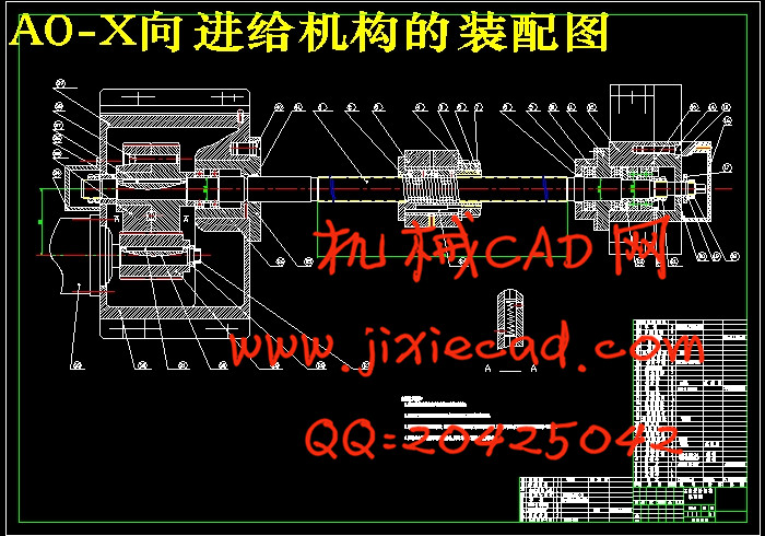
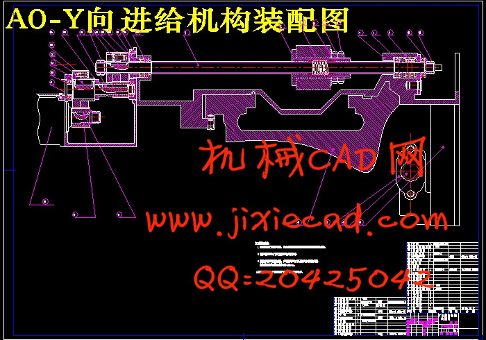
本文设计分析了超声精密铣床的发展现状和研究超声精密铣床的意义及超声精密铣床机构尺寸对铣床性能的影响。设计内容主要包括了总体方案及超声主轴箱设计,进给箱设计,液压系统和超声部分设计。
关键词:精密铣床 超声装置
Abstract
Today's various advanced materials in the aerospace industry, chemical industry, military, mechanical, electronic electric appliance and precision manufacturing areas to be more widely used. But, for these materials, such as high strength, high hardness and high brittle advanced ceramic materials, using the traditional mechanical processing way, processing difficult and can meet the requirements of processing. Ultrasonic machining technology is a kind of ultrasonic vibration used in precision or ultra-precision processing technology, especially in superhard materials, composite materials processing hard showed superiority, with low cutting force, low temperature and low cutting the surface roughness, be processing components have good wear resistance and corrosion resistance. So precision ultrasound milling machine will create quality more excellent products.
This paper analyzes the design of ultrasonic precision milling machine development present situation and research the significance and the ultrasonic precision milling machine ultrasonic precision milling machine dimensions of the institutions influence on the performance of the milling machine. Design content mainly includes the overall scheme and the ultrasonic spindle box design, the box design, hydraulic system and ultrasonic part of the design.
Key words: precision milling machine Ultrasound device
目 录
1 绪论 - 1 -
1.1数控技术与数控机床 - 1 -
1.2数控机床的特点及发展趋式 - 2 -
1.3数控超声铣床与其进给系统 - 7 -
1.4对进给传动系统的要求 - 9 -
1.5总体设计方案的拟定 - 14 -
2 机床横向进给系统机械部分计算与设计 - 16 -
2.1技术要求 - 16 -
2.2总体设计方案 - 16 -
2.3滚珠丝杠螺母副的选型和计算 - 17 -
2.3.1主切削力及其切削分力计算 - 17 -
2.3.2动载强度计算 - 18 -
2.3.3静强度计算 - 19 -
2.3.4滚珠丝杆支承选择 - 19 -
2.3.5压杆稳定性 - 20 -
2.3.6临界转速校核 - 21 -
2.3.7额定寿命的校核 - 22 -
2.4计算滚珠丝杠螺母副的轴向负载力 - 23 -
2.5滚珠丝杠的动载荷计算与直径估算 - 24 -
2.5.1确定滚珠丝杠的导程 - 24 -
2.5.2计算滚珠丝杠螺母副的平均转速和平均载荷 - 24 -
2.5.3确定滚珠丝杠预期的额定动载荷
2.6齿轮及转矩的有关计算 - 30 -
2.7滚珠丝杠螺母副的承载能力校验 - 32 -
2.7.1滚珠丝杆螺母副临界压缩载荷的校验 - 32 -
2.8计算机械传动系统的刚度 - 33 -
2.8.1机械传动系统的刚度计算 - 33 -
2.8.2传动系统综合刚度计算 - 33 -
2.9滚珠丝杠螺母副扭转刚度的计算 - 37 -
2.10驱动电动机的选型与计算 - 37 -
2.11计算折算到电动机轴上的负载力矩 - 38 -
2.12计算坐标轴折算到电动机轴上的各种所需力矩 - 38 -
2.13选择驱动电动机的型号 - 43 -
2.14滚珠丝杠螺母副的规格型号 - 44 -
2.15联轴器的选用 - 44 -
3 导轨的设计及滚珠丝杠螺母副间隙消除和预紧 - 46 -
3.1导轨的设计 - 46 -
3.1.1滚动导轨 - 46 -
3.1.2滚珠丝杠螺母副间隙消除和预紧 - 49 -
毕业设计总结 - 52 -
致 谢 - 54 -
参考文献 - 55 -


