设计简介
摘要
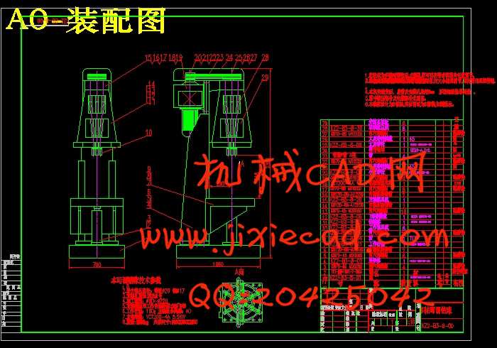
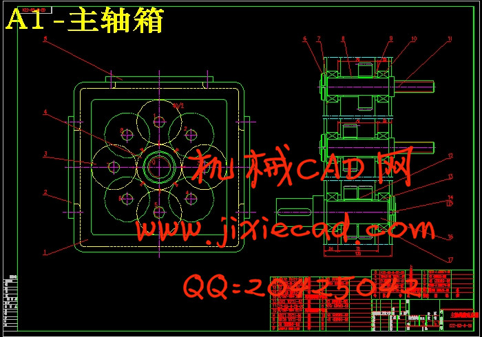
本设计是关于可变轴距多轴钻床的设计。设计一种钻床用钻轴均布可调多轴头。该多轴头各轴在圆周方向均布却可方便地沿直径方向同步调整,普通钻床为单轴机床,但安装上多轴箱就会成为多轴的钻床,改造成多轴钻床后,能大大地缩短加工时间,提高生产效率。本设计涉及一种可调间距的多轴钻床,包括机身,底座,工作台,主电机,主轴箱设置在机身上并位于工作台的上方,所述的主轴箱内设有万向节,万向节的上端通过齿轮或带轮与主电机相连接,万向节的下端与钻头主轴相连接,设计内容包括齿轮分布与选用、轴的设计、多轴箱的选用、导向装置设计等。不过国内现在多轴钻床传动箱大都采用万向节连杆式传动结构,其缺点是钻杆位置调节由万向节和连杆实现,调节麻烦,调节位置不准确,万向节的存在还使传动箱的轴向尺寸增大,传动刚性很差,这些缺点都可使工件孔的位置精度和尺寸精度不易保证,造成装配困难。
关键词: 多轴钻床; 可调轴距; 多轴箱
KEY WORDS: multiple drill;adjust; multiple spindle heads
目录
摘要 I
Abstract II
第1章 绪 论 1
1.1 可变轴距多轴加工的介绍 1
1.2 多轴加工的应用 1
1.3 多轴加工优势 1
1.4 多轴加工的设备 1
1.4.1 多轴头 2
1.4.2 多轴箱 2
1.4.3 多轴钻床 2
1.4.4 自动更换主轴箱机床 2
1.5 可变轴距多轴加工趋势 3
第2章 可变轴距多轴钻床的概述 4
2.1 可变轴距多轴钻床的定义 4
2.2 可变轴距多轴加工的特点 4
2.3 可变轴距多轴钻床的工作原理 4
2.4 可调轴间距多轴头的结构 5
2.4.1 连接部分 5
2.4.2 传动部分 5
2.4.3 轴间距的调整部分 5
2.4.4 钻头的装夹部分 5
第3章 可调轴距多轴钻床总体设计 6
3.1 生产任务 6
3.2 可调多轴立式钻床的选型 6
3.2.1 计算所需电机功率 6
3.2.2 立式钻床的确定 7
3.2.3 立钻型专机设计计算书 8
第4章 多轴齿轮传动箱的设计 9
4.1 设计前的准备工作 9
4.2 传动系统的设计与计算 10
第5章 导向装置及接杆刀具的设计 15
5.1 导向装置组成 15
5.2 接杆刀具 15
总结 16
参考文献 17
致谢 18
本设计是关于可变轴距多轴钻床的设计。设计一种钻床用钻轴均布可调多轴头。该多轴头各轴在圆周方向均布却可方便地沿直径方向同步调整,普通钻床为单轴机床,但安装上多轴箱就会成为多轴的钻床,改造成多轴钻床后,能大大地缩短加工时间,提高生产效率。本设计涉及一种可调间距的多轴钻床,包括机身,底座,工作台,主电机,主轴箱设置在机身上并位于工作台的上方,所述的主轴箱内设有万向节,万向节的上端通过齿轮或带轮与主电机相连接,万向节的下端与钻头主轴相连接,设计内容包括齿轮分布与选用、轴的设计、多轴箱的选用、导向装置设计等。不过国内现在多轴钻床传动箱大都采用万向节连杆式传动结构,其缺点是钻杆位置调节由万向节和连杆实现,调节麻烦,调节位置不准确,万向节的存在还使传动箱的轴向尺寸增大,传动刚性很差,这些缺点都可使工件孔的位置精度和尺寸精度不易保证,造成装配困难。
关键词: 多轴钻床; 可调轴距; 多轴箱
Abstract
This design is about the variable wheelbase multi-axis drilling machine design. Introduction of a drilling machine drill shaft can be adjustable multi spindle heads. The multiple spindle axis in are uniformly distributed in the circumference direction can easily along the diameter direction synchronous adjustment, the ordinary drill is a single axis machine tool, but mounted on the spindle becomes a multi-axis drilling machine, transformed into a machine, can greatly shorten the processing time, improve production efficiency. The utility model relates to a adjustable multi spindle drilling machine, comprising a body, do more, work table, the main motor, the spindle box is arranged in the body and is positioned on the worktable, wherein the spindle box is provided with a universal joint, the upper end of the universal joint through gear or belt wheel is connected with the main motor, universal joint the lower end of the drill bit is connected with the main shaft, the design includes the selection and distribution of gear wheel, shaft design, selection of the multiple spindle heads, guiding device design. But now the domestic machine transmission box adopts universal joint connecting rod type transmission structure, its disadvantages are the drill rod position adjustment by the universal joint and the connecting rod to realize the trouble, regulation, regulation of position is not accurate, universal existence also causes gearbox axial size increases, drive rigidity is poor, these shortcomings can make the workpiece bore location accuracy and dimensional accuracy can not be guaranteed, causing difficulty in fitting.KEY WORDS: multiple drill;adjust; multiple spindle heads
目录
摘要 I
Abstract II
第1章 绪 论 1
1.1 可变轴距多轴加工的介绍 1
1.2 多轴加工的应用 1
1.3 多轴加工优势 1
1.4 多轴加工的设备 1
1.4.1 多轴头 2
1.4.2 多轴箱 2
1.4.3 多轴钻床 2
1.4.4 自动更换主轴箱机床 2
1.5 可变轴距多轴加工趋势 3
第2章 可变轴距多轴钻床的概述 4
2.1 可变轴距多轴钻床的定义 4
2.2 可变轴距多轴加工的特点 4
2.3 可变轴距多轴钻床的工作原理 4
2.4 可调轴间距多轴头的结构 5
2.4.1 连接部分 5
2.4.2 传动部分 5
2.4.3 轴间距的调整部分 5
2.4.4 钻头的装夹部分 5
第3章 可调轴距多轴钻床总体设计 6
3.1 生产任务 6
3.2 可调多轴立式钻床的选型 6
3.2.1 计算所需电机功率 6
3.2.2 立式钻床的确定 7
3.2.3 立钻型专机设计计算书 8
第4章 多轴齿轮传动箱的设计 9
4.1 设计前的准备工作 9
4.2 传动系统的设计与计算 10
第5章 导向装置及接杆刀具的设计 15
5.1 导向装置组成 15
5.2 接杆刀具 15
总结 16
参考文献 17
致谢 18


