设计简介
(1)氨气体积流率:7000Nm3/h;进口温度:144℃;
(2)氨气出口温度:57℃;允许压降:△P=3920N/m2
(3)换热介质为水,进口温度30℃;出口温度37℃
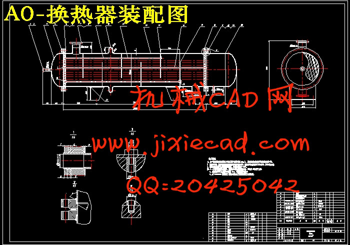
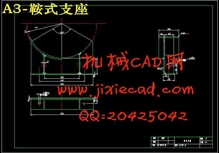
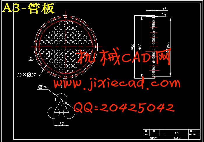
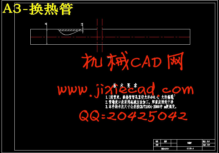
【摘要】本设计说明书是关于换热器的设计,主要是进行了换热器的工艺计算、换热器的结构和强度设计。设计的前半部分是工艺计算部分,主要是根据给定的设计条件估算换热面积,从而进行换热器的选型,校核传热系数,计算出实际的换热面积,最后进行压力降和壁温的计算。设计的后半部分则是关于结构和强度的设计,主要是根据已经选定的换热器型式进行设备内各零部件(如接管、折流板、定距管、钩圈、管箱等)的设计,包括:材料的选择、具体尺寸确定、确定具体位置、管板厚度的计算、浮头盖和浮头法兰厚度的计算、开孔补强计算等。最后设计结果可通过4张图表现出来。
【关键词】 换热器 接管 折流板 定距管
【Abstract】:The design manual is about heat exchanger, which included technology calculate of heat exchanger, the structure and intensity of heat exchanger.
The first part of design is the technology calculation process. Mainly, the process of technology calculate is according to the given design conditions to estimate the heat exchanger area, and then, select a suitable heat exchanger to check heat transfer coefficient ,just for the actual heat transfer area .Meanwhile the process above still include the pressure drop and wall temperature calculation . The second half of the design is about the structure and intensity of the design. This part is just on the selected type of heat exchanger to design the heat exchanger’s components and parts ,such as vesting ,baffled plates, the distance control tube, circle hook, tube boxes. This part of design mainly include:the choice of materials,identify specific size, identify specific location, the thickness calculation of tube sheet, the thickness calculation of floating head planting and floating head flange, the opening reinforcement calculation etc. In the end, the final design results through four maps to display.
【Keywords】:heat exchanger ,vesting ,baffled plates, the distance control tube
目录
1.前言 1
1.1氨气的性质 1
1.1.1氨气的用途 1
1.1.2合成氨技术 1
1.2换热器的性质 2
1.2.1换热器的发展历史 2
1.2.2换热器的国内发展现状 4
1.2.3换热器产业发展趋势 5
1.2.4换热器研究的主攻方向 5
2.设计任务 6
2.1设计内容 6
2.2设计要求 6
3.设计方案 7
3.1确定设计方案 7
3.2换热器的选型 7
3.2.1列管式换热器 7
3.2.2固定管板式换热器 8
3.2.3浮头式换热器 8
3.2.4U型管换热器 9
3.2.5填料函式换热器 9
3.2.6换热器最终选型 10
3.3换热器内冷热流体通道的选择 10
3.4流速的选择 10
3.5.1换热管的选用 11
3.5.2管子的排列 11
4.物性数据 12
4.1定性温度 12
4.2物性数据 12
5.工艺设计说明 13
5.1估算传热面积A 13
5.1.1换热器热负荷及冷却介质消耗量的计算 13
5.1.2计算平均温度差,并确定管程数。选取逆流流向,先按单壳程单管程考虑,计算出平均温度差。 13
5.1.3按经验数值初选总传热系数 14
14
5.1.4现估算传热面积为: 14
5.2主要工艺及结构基本参数的计算 14
5.2.1换热管数量及长度的确定 14
5.2.2管子的排列方式及管子与管板的连接方式的选定 14
5.2.3计算外壳体内直径 14
14
5.2.4画出管排列图 15
5.2.5计算实际传热面积 及过程的总传热系数
 15
15
5.2.6折流板 15
5.2.7拉杆的直径和数量与定距管的选定 16
5.2.8温度补偿圈的选用 16
5.2.9列出所设计换热器的结构基本参数 16
5.3换热器主要结构尺寸与接管尺寸的确定 17
5.3.1壳体壁厚的确定 17
5.3.2流体进出口接管的直径计算 17
5.4管、壳程压强降的校验 18
5.4.1管程压降 18
5.4.2壳程压降(冷却水走壳程) 18
5.5总传热系数的校验 20
6.主体构件的设计和连接 22
6.1管束分程及管壳分程情况 22
6.2管板的选取 23
6.3管箱与封头 24
6.4折流板 24
6.5支承板 25
6.6拉杆与定距管 26
6.7支座 27
6.7.1立式支座 27
6.7.2卧式支座 27
7辅助结构的选用 28
7.1缓冲挡板 28
7.2导流筒 28
7.3排气,排液孔 28
7.4 膨胀节的选用与计算 29
8.总结与展望 30
8.1 总结 30
8.2 展望 31
参考文献 32
致谢 33
(2)氨气出口温度:57℃;允许压降:△P=3920N/m2
(3)换热介质为水,进口温度30℃;出口温度37℃
【摘要】本设计说明书是关于换热器的设计,主要是进行了换热器的工艺计算、换热器的结构和强度设计。设计的前半部分是工艺计算部分,主要是根据给定的设计条件估算换热面积,从而进行换热器的选型,校核传热系数,计算出实际的换热面积,最后进行压力降和壁温的计算。设计的后半部分则是关于结构和强度的设计,主要是根据已经选定的换热器型式进行设备内各零部件(如接管、折流板、定距管、钩圈、管箱等)的设计,包括:材料的选择、具体尺寸确定、确定具体位置、管板厚度的计算、浮头盖和浮头法兰厚度的计算、开孔补强计算等。最后设计结果可通过4张图表现出来。
【关键词】 换热器 接管 折流板 定距管
【Abstract】:The design manual is about heat exchanger, which included technology calculate of heat exchanger, the structure and intensity of heat exchanger.
The first part of design is the technology calculation process. Mainly, the process of technology calculate is according to the given design conditions to estimate the heat exchanger area, and then, select a suitable heat exchanger to check heat transfer coefficient ,just for the actual heat transfer area .Meanwhile the process above still include the pressure drop and wall temperature calculation . The second half of the design is about the structure and intensity of the design. This part is just on the selected type of heat exchanger to design the heat exchanger’s components and parts ,such as vesting ,baffled plates, the distance control tube, circle hook, tube boxes. This part of design mainly include:the choice of materials,identify specific size, identify specific location, the thickness calculation of tube sheet, the thickness calculation of floating head planting and floating head flange, the opening reinforcement calculation etc. In the end, the final design results through four maps to display.
【Keywords】:heat exchanger ,vesting ,baffled plates, the distance control tube
目录
1.前言 1
1.1氨气的性质 1
1.1.1氨气的用途 1
1.1.2合成氨技术 1
1.2换热器的性质 2
1.2.1换热器的发展历史 2
1.2.2换热器的国内发展现状 4
1.2.3换热器产业发展趋势 5
1.2.4换热器研究的主攻方向 5
2.设计任务 6
2.1设计内容 6
2.2设计要求 6
3.设计方案 7
3.1确定设计方案 7
3.2换热器的选型 7
3.2.1列管式换热器 7
3.2.2固定管板式换热器 8
3.2.3浮头式换热器 8
3.2.4U型管换热器 9
3.2.5填料函式换热器 9
3.2.6换热器最终选型 10
3.3换热器内冷热流体通道的选择 10
3.4流速的选择 10
3.5.1换热管的选用 11
3.5.2管子的排列 11
4.物性数据 12
4.1定性温度 12
4.2物性数据 12
5.工艺设计说明 13
5.1估算传热面积A 13
5.1.1换热器热负荷及冷却介质消耗量的计算 13
5.1.2计算平均温度差,并确定管程数。选取逆流流向,先按单壳程单管程考虑,计算出平均温度差。 13
5.1.3按经验数值初选总传热系数
5.1.4现估算传热面积为: 14
5.2主要工艺及结构基本参数的计算 14
5.2.1换热管数量及长度的确定 14
5.2.2管子的排列方式及管子与管板的连接方式的选定 14
5.2.3计算外壳体内直径
5.2.4画出管排列图 15
5.2.5计算实际传热面积
5.2.6折流板 15
5.2.7拉杆的直径和数量与定距管的选定 16
5.2.8温度补偿圈的选用 16
5.2.9列出所设计换热器的结构基本参数 16
5.3换热器主要结构尺寸与接管尺寸的确定 17
5.3.1壳体壁厚的确定 17
5.3.2流体进出口接管的直径计算 17
5.4管、壳程压强降的校验 18
5.4.1管程压降 18
5.4.2壳程压降(冷却水走壳程) 18
5.5总传热系数的校验 20
6.主体构件的设计和连接 22
6.1管束分程及管壳分程情况 22
6.2管板的选取 23
6.3管箱与封头 24
6.4折流板 24
6.5支承板 25
6.6拉杆与定距管 26
6.7支座 27
6.7.1立式支座 27
6.7.2卧式支座 27
7辅助结构的选用 28
7.1缓冲挡板 28
7.2导流筒 28
7.3排气,排液孔 28
7.4 膨胀节的选用与计算 29
8.总结与展望 30
8.1 总结 30
8.2 展望 31
参考文献 32
致谢 33


