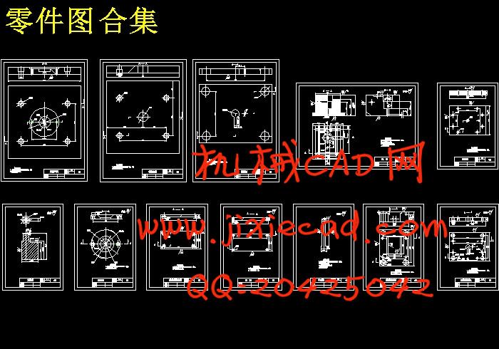
设计简介
摘 要
本设计题目为用UG3.0进行连接座注塑模具设计,体现了UG3.0在注塑模具设计过程中的一般方法、要求及发展方向,具有一定的设计意义。
本设计是注塑模具设计中较简单的一种。设计过程中首先根据设计任务书中产品二维图,对产品进行造型设计,然后通过对产品的特征分析确定模具设计思路和设计方案。最后,根据产品模型,运用UG3.0中Mold Wizard模块对连接座模具进行设计。
UG3.0/Mold Wizard用全参数的方法自动处理在模具设计中耗时且难做的部分,并且产品参数的改变将会反馈回模具设计, 自动更新所有相关的模具部件,它与UG3.0/Wave和Unigraphics主模型技术组合在一起设计模具,功能强大。
本产品结构简单,但既有通孔又含侧孔,模具设计过程中,在分型操作时需要创建补片曲面,创建分型面时需要进行分型面的转换。
关键词:注塑成型 UG软件 造型 模具设计
ABSTRACT
The topic of the design is to design a injection mold of connector with the UG3.0 The design proves the general method、the request and the development direction of injection mold design, which have certain design meaning.
The design is a simple one in the injection mold design. First ,we design a mold of the product according X-Y scheme.Then we analyze the characteristic of the product and determine the idea and the scheme of design .By the last ,we can design the injection mold of the connector according to the product mold with the help of the Mold Wizard in UG3.0.
The UG3.0/Mold Wizard uses the method auto of whole parameterses a processing at the mold design in consume and difficult do of part, and the change of product parameter will the feedback return to mold design, automatically renew all related mold partses, it combines with UG3.0/Wave and the main model technique of the Unigraphics to together design a molding tool, and the function is strong.
This product shape is simple, but it currents the bore and contains side bore again,.In the process of the design , It needs to establish to repair a slice of curved face when the cent type operate, which also needs to carry on the type of cent the conversion of the noodles while establishing the type of cent noodles.
Keyword:injection moulding the UG software the shape design mold design
目 录
摘要
绪论……………………………………………………………………………………1
第1章 产品结构及注塑工艺分析……………………………………………………6
1.1 分型面的选择……………………………………………………………………6
1.2 型腔布局…………………………………………………………………………7
1.3 浇注系统设计……………………………………………………………………7
1.3.1主流道设计………………………………………………………………………7
1.3.2 主流道衬套设计………………………………………………………………7
1.3.3 定位环设计……………………………………………………………………8
1.4 冷却系统设计……………………………………………………………………8
1.5 推出机构设计……………………………………………………………………8
第2章 产品造型设计…………………………………………………………………10
第3章 连接座注塑模具设计…………………………………………………………14
3.1 装载产品………………………………………………………………………14
3.2 模具坐标系………………………………………………………………………15
3.3 设定收缩率………………………………………………………………………15
3.4 设定工件…………………………………………………………………………16
3.5 零件修补…………………………………………………………………………16
3.6 分型………………………………………………………………………………17
3.7 添加模架…………………………………………………………………………20
3.8 添加标准部件……………………………………………………………………22
3.9 冷却系统设计……………………………………………………………………23
3.10 浇注系统设计…………………………………………………………………27
3.11 成型部件修剪…………………………………………………………………27
3.11.1 小型芯修剪…………………………………………………………………27
3.11.2 大型芯修剪…………………………………………………………………28
3.11.3 型腔修剪……………………………………………………………………30
3.12 建腔……………………………………………………………………………31
3.12.1 型腔板建腔…………………………………………………………………31
3.12.2 浇注系统建腔………………………………………………………………32
3.12.3 冷却系统建腔………………………………………………………………32
3.12.4 型芯固定板和推件板建腔…………………………………………………32
3.13 添加螺钉………………………………………………………………………32
第4章 模具结构的虚拟装配及二维工程图…………………………………………34
第5章 模具零件清单导出……………………………………………………………36
结束语………………………………………………………………………………37
致谢…………………………………………………………………………………39
参考文献………………………………………………………………………………40
附录…………………………………………………………………………………


