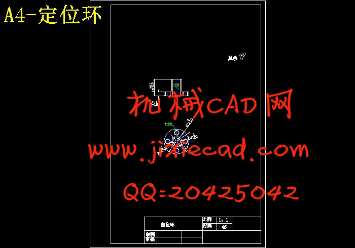
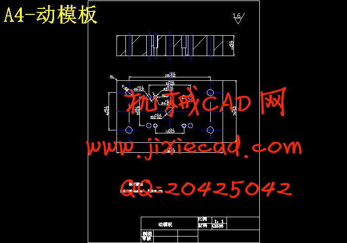
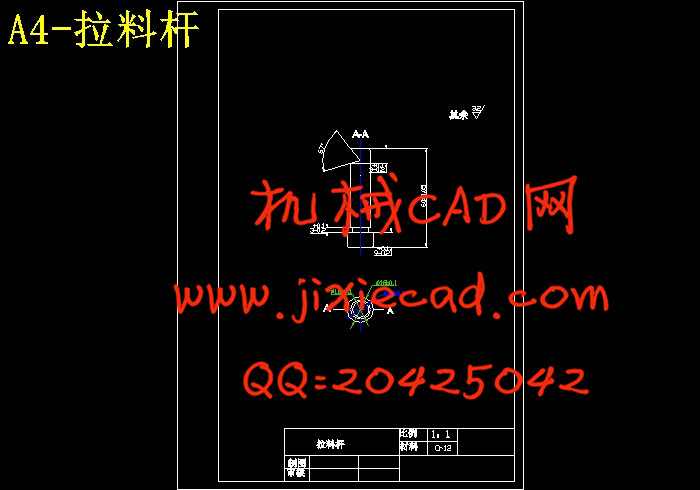
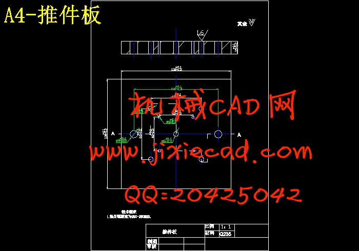
设计简介
摘要
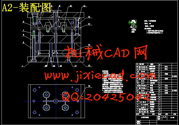
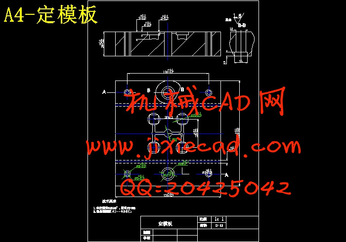
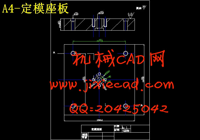
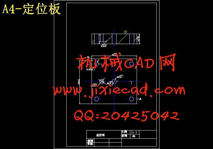
热塑性塑件的注塑,是注射模中最基本的一种,根据计算机按钮的造型,分析可得,结构比较简单,没有特殊工艺要求,公差等级低,易于实现大批量注塑生产,总体构思过程;首先收集资料,根据塑件结构工艺性、材料收缩率、注射机器的规格、寿命措施、分型面设置、浇口形式、本厂的加工设备和技术、其他相关资料等。其次是模具结构,型腔、型芯配置及结构、冷却系统、抽芯机构、推出机构、浇道系统、排气方式、模具材料、模架形式、标准间的选用。
根据PS 的性能,通过查阅机械制造手册,合理控制塑件的收缩率,确定模具型腔、型芯的设计尺寸及强度计算校核,锁模力平衡的确定、浇道系统设计、浇道和浇口平衡校核;计算机按钮结构不需要侧抽芯机构,抽芯力的计算;冷却系统设计;推出机构设计、计算推顶力;排气方式选用。
关键字:计算机按钮 浇道系统 分型面
Abstract
Thermoplastic injection molding of plastic parts, injection mold is the most basic kind of button in accordance with computer modeling, analysis available, relatively simple structure, there is no special process requirements, a low tolerance level, easy to achieve high-volume injection molding production, the overall idea of the process; First of all, the collection of information technology in accordance with the structure of plastic parts, material shrinkage, injection machine specifications, life measures set up surface, gate the form of factory processing equipment and technology, other relevant information. Followed by the mold structure, cavity, core configuration and structure, cooling system, core-pulling mechanism, the introduction agencies, runner system, the exhaust means, mold materials, mold form of the choice of standard room.
Reasonable control of the contraction rate of plastic parts to determine the mold cavity, the design of core size and strength check calculation, runner and gate balance check; computer side buttons do not need to draw the structure of the core institutions, the calculation of core-pulling power; cooling system design; the introduction of mechanical design, push the top edge computing; exhaust mode selection.
Keywords: plastic parts of the structure of process systems design runner runner system cavity, core
目 录
1.绪论………………………………………………………………………………1
2.塑件的工艺性分析………………………………………………………………6
2.1.1塑料特性分析 ………………………………………………………………6
2.1.2塑件材料成型能 ……………………………………………………………7
2.1.3.塑件成型工艺参数的确定…………………………………………………7
3模具结构方案及模架的选择……………………………………………………8
3.1模具的基本结构………………………………………………………………8
3.2确定行腔数目及布置…………………………………………………………8
3.3选择分型面……………………………………………………………………9
3.4确定浇注系统…………………………………………………………………9
3.4.1浇口位置的选择……………………………………………………………10
3.5成型零件结构设计……………………………………………………………11
3.6推出方式………………………………………………………………………12
3.7确定模温调节系统……………………………………………………………13
3.8确定排气方式…………………………………………………………………13
4. 选择成型设备并校核有关参数………………………………………………14
4.1计算塑件的体积………………………………………………………………14
4.2计算塑件的质量………………………………………………………………14
4.3有关参数………………………………………………………………………14
5. 模具设计的有关计算…………………………………………………………15
5.1成型零件工作尺寸的计算……………………………………………………15
6. 模具的试模与修模……………………………………………………………17
6.1塑件粘着模腔…………………………………………………………………17
6.2粘着模芯………………………………………………………………………17
6.3 粘着主流道 …………………………………………………………………17
6.4成型缺陷………………………………………………………………………18
6.4.1 注射填充不足 ……………………………………………………………18
6.4.2溢边…………………………………………………………………………18
6.4.3制件尺寸不准确……………………………………………………………19
7. 总结……………………………………………………………………………20
8. 致谢……………………………………………………………………………21
9. 参考文献………………………………………………………………………22


