设计简介
摘 要
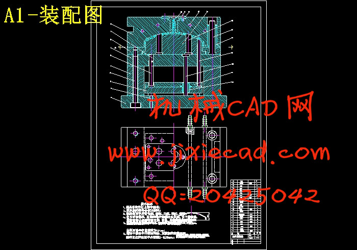
本文介绍了壳体塑料模具的设计过程。本设计对塑件在模具中的位置和分型面位置、选择浇注系统与排气系统、成型零件的结构、合模导向机构、推出机构、温度调节系统的设计方案做了充分的论证,并优化选取最合理的设计方案。带有脱模斜度的孔,则利用塑件的脱模斜度替代侧抽芯,简化了模具结构。通过对型芯支承板和型腔板的计算,保证了模具的正常使用,优化了模具的结构设计,使得模具结构紧凑。
关键词:注射模;挤出模;;浇口套;排气槽;分型面;推杆。
Keywords: injection mould; processing technology;sprue bush;air vent;parting line;ejector pin .
绪 论 - 1 -
1 塑件分析与模具材料和注射机的选取 - 4 -
1.1 塑件结构和技术要求的分析 - 4 -
1.1.1 塑件工艺规程的编制 - 4 -
1.2 塑件的工艺性分析 - 5 -
1.2.1 塑件的原材料分析 - 5 -
1.2.2 塑件的结构和尺寸精度及表面质量分析 - 5 -
1.3 计算塑件的质量和体积 - 6 -
1.3.1 根据塑件的质量选择注塑机及确定型腔数 - 6 -
1.3.2 注射机的选用 - 6 -
1.4 塑料材料的成型特性与工艺参数 - 7 -
1.5 模具材料的选取及热处理 - 8 -
2 确定模具的结构方案 - 10 -
2.1 确定塑件在模具中的位置和分型面位置 - 10 -
2.1.1 模腔数量的确定 - 10 -
2.1.2 分型面的选择以及型腔的排列方式的确定 - 11 -
2.1.2.1分型面的选择 - 11 -
2.2.1 主流道设计 - 12 -
2.3 成型零件的结构设计 - 13 -
2.3.1 凹模 - 13 -
2.3.2 凸模和型芯 - 16 -
2.3.3. 凸模与固定板连接方式如图所示 : - 17 -
2.4 合模导向机构设计 - 17 -
2.4.1 导向机构的作用 - 17 -
2.4.2 导柱导向机构 - 18 -
2.4.2.1 导柱 - 18 -
2.5 推出机构设计 - 19 -
2.5.1 推杆推出机构 - 20 -
2.5.2 推件板推出机构 - 20 -
3 工作尺寸的计算和注射机的校核 - 21 -
3.1 成型零件的计算和选取 - 21 -
3.1.1 型腔板尺寸的计算 - 23 -
3.1.2 型腔板的最小尺寸计算 - 25 -
3.1.3 型芯固定板尺寸的计算 - 25 -
3.2 模架各板尺寸的选取与校核 - 26 -
3.2.1 模架各板尺寸的选取 - 26 -
3.2.2 对模架各板的校核 - 26 -
3.3 注射机的校核 - 27 -
3.3.1 校核锁模力 - 27 -
3.3.2 校核注射压力 - 28 -
3.3.3 校核模具的闭合厚度 - 28 -
4 模具加热和冷却系统的设计 - 29 -
4.1、冷却系统的设计原则与冷却系统的结构 - 29 -
5 模具的安装与调试 - 31 -
5.1 模具的安装: - 31 -
5.2 模具的调试 - 31 -
设计总结 - 33 -
致谢 - 34 -
参考文献 - 35 -
本文介绍了壳体塑料模具的设计过程。本设计对塑件在模具中的位置和分型面位置、选择浇注系统与排气系统、成型零件的结构、合模导向机构、推出机构、温度调节系统的设计方案做了充分的论证,并优化选取最合理的设计方案。带有脱模斜度的孔,则利用塑件的脱模斜度替代侧抽芯,简化了模具结构。通过对型芯支承板和型腔板的计算,保证了模具的正常使用,优化了模具的结构设计,使得模具结构紧凑。
关键词:注射模;挤出模;;浇口套;排气槽;分型面;推杆。
Abstract
This text introduced the mould design process of the shells. Determining the plastic part in mould and selection of the parting line, the feed and runner system design, the core/cavity creation structure design, the guide pin and guide bush , the plastic ejector structure , external undercuts and cooling and ejection system designing, they all be analyzed in this text, and choose the best design. With the hole in the side of product deal with Angle Pin, if the hole oblique, make the use of tilted detrusion straight, so the structure of the mould will be simplify. By the caculate of the cavity plate and backing plate, make the mould used working order, optimized the mould structure, make the mould structure compact. And we has demonstrated the structure of the mould in the design of the blow mould, such as the form of knife edge and the cooling system. We has compared the form of the co-extrusion mould ,and we has selected the type of the co-extrusion machine accord the need of the producing condiction of the product.Keywords: injection mould; processing technology;sprue bush;air vent;parting line;ejector pin .
绪 论 - 1 -
1 塑件分析与模具材料和注射机的选取 - 4 -
1.1 塑件结构和技术要求的分析 - 4 -
1.1.1 塑件工艺规程的编制 - 4 -
1.2 塑件的工艺性分析 - 5 -
1.2.1 塑件的原材料分析 - 5 -
1.2.2 塑件的结构和尺寸精度及表面质量分析 - 5 -
1.3 计算塑件的质量和体积 - 6 -
1.3.1 根据塑件的质量选择注塑机及确定型腔数 - 6 -
1.3.2 注射机的选用 - 6 -
1.4 塑料材料的成型特性与工艺参数 - 7 -
1.5 模具材料的选取及热处理 - 8 -
2 确定模具的结构方案 - 10 -
2.1 确定塑件在模具中的位置和分型面位置 - 10 -
2.1.1 模腔数量的确定 - 10 -
2.1.2 分型面的选择以及型腔的排列方式的确定 - 11 -
2.1.2.1分型面的选择 - 11 -
2.2.1 主流道设计 - 12 -
2.3 成型零件的结构设计 - 13 -
2.3.1 凹模 - 13 -
2.3.2 凸模和型芯 - 16 -
2.3.3. 凸模与固定板连接方式如图所示 : - 17 -
2.4 合模导向机构设计 - 17 -
2.4.1 导向机构的作用 - 17 -
2.4.2 导柱导向机构 - 18 -
2.4.2.1 导柱 - 18 -
2.5 推出机构设计 - 19 -
2.5.1 推杆推出机构 - 20 -
2.5.2 推件板推出机构 - 20 -
3 工作尺寸的计算和注射机的校核 - 21 -
3.1 成型零件的计算和选取 - 21 -
3.1.1 型腔板尺寸的计算 - 23 -
3.1.2 型腔板的最小尺寸计算 - 25 -
3.1.3 型芯固定板尺寸的计算 - 25 -
3.2 模架各板尺寸的选取与校核 - 26 -
3.2.1 模架各板尺寸的选取 - 26 -
3.2.2 对模架各板的校核 - 26 -
3.3 注射机的校核 - 27 -
3.3.1 校核锁模力 - 27 -
3.3.2 校核注射压力 - 28 -
3.3.3 校核模具的闭合厚度 - 28 -
4 模具加热和冷却系统的设计 - 29 -
4.1、冷却系统的设计原则与冷却系统的结构 - 29 -
5 模具的安装与调试 - 31 -
5.1 模具的安装: - 31 -
5.2 模具的调试 - 31 -
设计总结 - 33 -
致谢 - 34 -
参考文献 - 35 -


