设计简介
摘 要
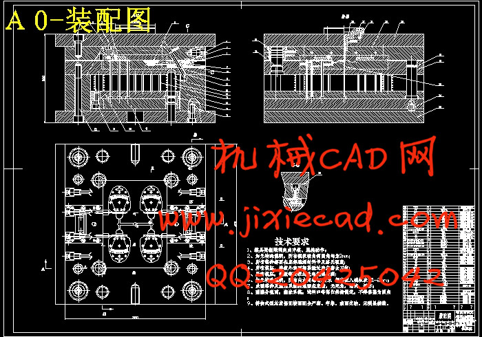
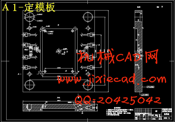
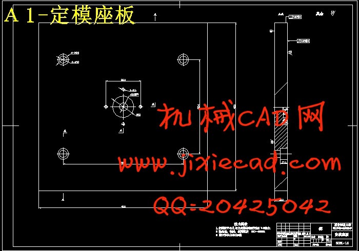
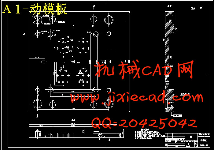
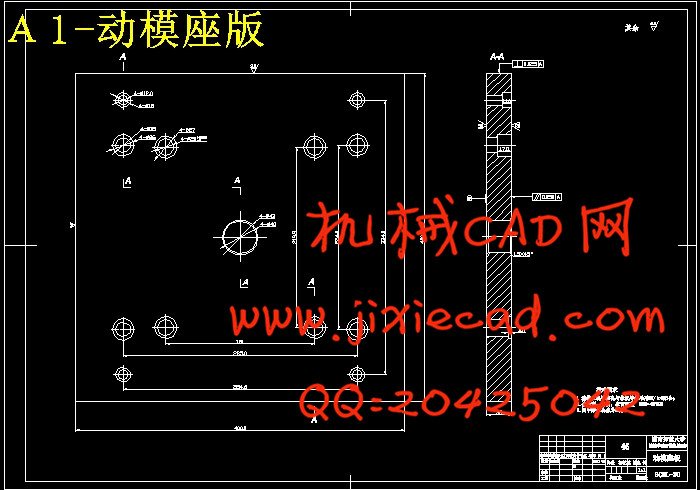
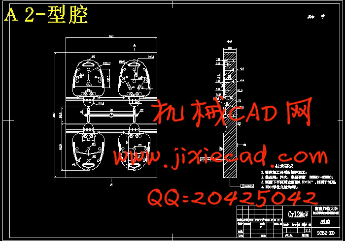
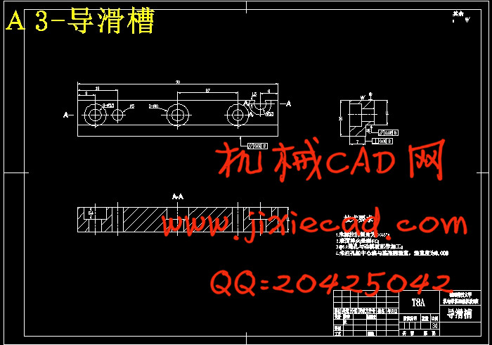
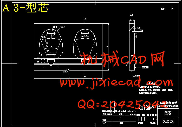
通过对手机旅行充电器夹板工艺的正确分析,设计了一副一模四腔的塑料模具。在本套模具设计过程中详细地叙述了模具成型零件包括定模板、前模仁、动模板、后模仁、镶块、导杆、斜导柱、滑块等的设计过程,重要零件的工艺参数的选择与计算,及推出机构、浇注系统以及侧向分型、抽芯机构的设计过程,利用当今业界广泛应用的绘图软件pro/E、AutoCAD分析了各方案可行性,并绘出了整套模具,并对成型零件进行了计算。分析并选择了各个成型零件的材料,对其刚度,强度进行了校核,并对试模与产品缺陷作了介绍,最后进行了对模具工艺性与经济性分析。
关键词:侧向分型;多型腔。
The plastic molds of The mobile travel battery charger clamping plank
Abstract
Through to the mobile travel battery charger clamping plank craft correct analysis, has designed mold four cavity plastic molds. (In this set of mold design process) narrated the mold to take shape in detail the components after to decide the template, the cover mold kernel, moves the template, the mold kernel, inlays the block, the guide rod, the slanting guide pillar, the slide and so on the design process, the important components craft parameter choice and the computation, and promoted the organization, pours systematic as well as the lateral minute, pulls out the core organization the design process, use field widespread application cartography software pro/E, AutoCAD have analyzed various plans feasibility now, and drew the entire wrap mold, and to took shape the components to carry on the computation. Analyzed and chooses has taken shape one by one the components material, to its rigidity, the intensity has carried on the examination, and has made the introduction to the experimental mold and the product flaw, finally has carried on to mold technology capability and efficient analysis.
Key words: Petal mold modules; Excessive casements。
手机旅行充电器上夹板注塑模具
目 录
摘 要……………………………………………………………………1
ABSTRACT……………………………………………………………...2
第一章 绪论……………………………………………………………..3
第二章 拟定模具结构形式……………………………………………5
2.1确定型腔数量及排列方式 ………………………………………5
2.1.1 塑件成型工艺性分析 ………………………………………5
2.1.2 脱模斜度 ……………………………………………………6
2.1.3 型腔数目及排列方式 ……………………………………6
2.2 模具结构形式的确定…………………………………………….8
第三章 注射机型号的确定……………………………………………8
3.1 注射量的计算 …………………………………………………8
3.2 塑件和流道凝料在分型面上的投影面积及所需锁摸力……8
3.3 注射机有关参数的校核 ………………………………………9
第四章 分型面位置的确定 …………………………………………10
第五章 浇注系统形式和浇口的设计…………………………………12
5.1 主流道设计……………………………………………………12
5.1.1 主流道尺寸…………………………………………………12
5.1.2 主流道衬套的形式…………………………………………13
5.1.3 主流道剪切速率校核………………………………………13
5.1.4 主流道衬套的固定…………………………………………14
5.2 分流道设计……………………………………………………14
5.2.1 分流道的布置形式…………………………………………14
5.2.2 分流道长度…………………………………………………15
5.2.3 分流道的形状、截面尺寸以及凝料体积…………………15
5.3 浇口的设计……………………………………………………17
5.4 排气槽的设计…………………………………………………18
第六章 模架的确定……………………………………………………19
第七章 成型零件的设计与计算………………………………………21
7.1 成型零件钢材选用……………………………………………21
7.2 凹模的结构设计………………………………………………22
7.3 凸模的结构设计………………………………………………22
7.4 成型零件工作尺寸的计算……………………………………23
7.5 模具强度的校核………………………………………………30
7.5.1 整体式矩形型腔侧壁厚度计算 …………………………30
7.5.2 整体式矩形型腔底板厚度计算……………………………32
第八章 导向机构的设计 ……………………………………………33
8.2 导柱导向机构…………………………………………………33
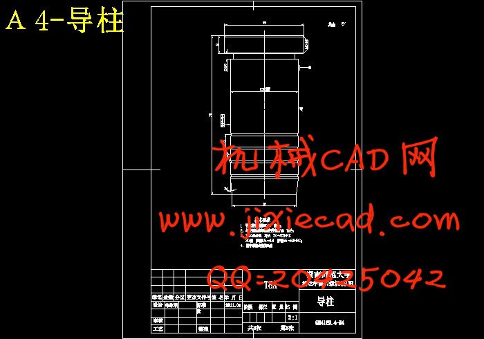
8.1.1 导柱…………………………………………………………33
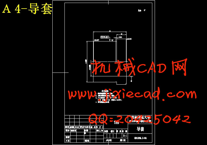
8.1.2 导套 ………………………………………………………35
第九章 脱模机构、复位机构的设计…………………………………37
9.1 推出机构的组成 ………………………………………………37
9.2 本模具的推出机构 ……………………………………………39
9.3 脱模阻力的计算 ………………………………………………40
9.4 复位机构设计 …………………………………………………41
第十章 侧向分型与抽芯机构的设计 ………………………………42
10.1 抽拔距与抽拔力及机构组成 ………………………………42
10.1.1 抽拔距 ……………………………………………………42
10.1.2 抽拔力 ……………………………………………………43
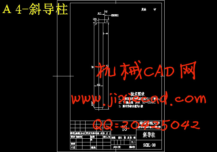
10.1.3 斜导柱驱动的结构组成 …………………………………44
10.2 斜导柱的长度和最小开模行程的计算 ……………………47
10.3 斜导柱的受力分析 …………………………………………48
第十一章 总结…………………………………………………………50
参考文献………………………………………………………………..51


