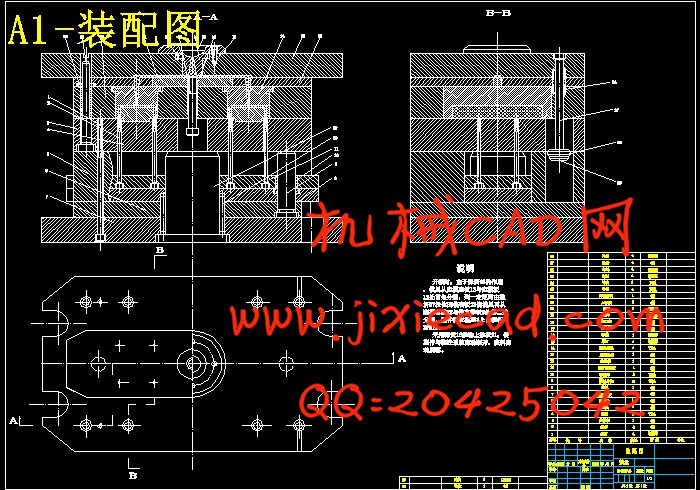
设计简介
摘要:注塑模具CAD技术是指在注塑模具设计过程中采用CAD系统来辅助设计人员进行模具设计,以便提高模具设计的水平和效率。注塑模具CAD系统是在通用CAD系统的基础上,加载了注塑模具知识和设计经验模块,支持注塑模具设计的基本流程。
随着科学的发展,各种产品的更新换代速度越来越快,而产品的更新是以新产品的造型设计和模具的设计、制造与更新为前提的。模具的设计是模具更新的基础,模具设计工作与产品的更新信息相关。传统的手工设计模式已经不能很好地适应时代的需要,计算机辅助设计与制造已成为许多大型CAD/CAM/CAE软件追求的目标。而在众多辅助设计制造软件中,Unigraphics 软件是当今世界较先进、面向制造业的综合软件。
本设计首先采用UG软件进行注塑件的三维实体造型,针对手机上盖的具体外形尺寸,应用基于特征的实体建模和自由形状建模等知识,使用体素特征、扫描特征、成形特征、特征操作等具体的操作步骤逐步生成手机上盖。其次,利用UG软件中的Mold wizard工具对手机上盖进行拆模,并且对手机上盖模具的模架、定位环、推杆、浇口、合模导向机构、抽芯机构、浇注系统、冷却系统等进行了设计。最后,利用UG软件中的CAM功能对凸模进行仿真加工并生成手机上盖凸模的NC加工程序。
关键词:注塑模具 UG 手机上盖 凸模
Abstract: CAD technology is the injection mold injection mold design process in the CAD system used to assist designers to mold design, mold design in order to improve the level and efficiency. Injection Mold CAD system is based on the general CAD system, load the injection mold design knowledge and experience in modules support the basic process of injection mold design.
With the development of science, the upgrading of various products faster and faster, while the product update is a new product modeling design and mold design, manufacturing and updated as the prerequisite. Mold mold design is the basis for updating, mold design and product-related updates. The traditional manual design model has not well adapted to the needs of the times, computer-aided design and manufacturing has become many large CAD / CAM / CAE software goal. Assisted in the design and manufacturing of many software, Unigraphics software is the world's more advanced and comprehensive software for the manufacturing industry.
The design of the first injection molded parts using UG software three-dimensional solid modeling,mobile shelters for the specific dimensions,application of feature-based modeling and free modeling the shape of knowledge, use of voxel features, scanning features, shape features, feature operation and other concrete steps to gradually build mobile phone cover. Secondly, the use of UG software Mold wizard tools mobile phone cover for form removal, and mold on the mobile phone cover mold, positioning ring, putter,gate, mold-oriented institutions, core pulling mechanism, gating system, cooling system is designed. Finally, UG CAM software features simulation of the punch process and generate the NC cell phone cover punch processing.
Keywords: Injection Mold UG Mobile phone cover Punch
目 录
1 引言
1.1 课题的依据和意义………………………………………………………(1)
1.2 注塑模具CAD技术概述…………………………………………………(1)
1.2.1 注塑模具CAD技术发展背景…………………………………………(1)
1.2.2 注塑模具CAD技术发展过程…………………………………………(2)
1.2.3 国内外注塑模具CAD技术研究现状…………………………………(4)
1.3 国内外塑料工业的发展概况……………………………………………(5)
1.4 塑料模国内外研究概况及发展趋势……………………………………(7)
1.5 模具加工CAM现状………………………………………………………(9)
1.6 UG软件在模具制造中的应用特点………………………………………(9)
1.7 本设计任务………………………………………………………………(10)
2 UG在模具设计中的应用
2.1 UG的概述…………………………………………………………………(11)
2.1.1 UG功能简介……………………………………………………………(11)
2.1.2 UG软件应用的特点……………………………………………………(12)
2.2 UG/Mold Wizard 工具及应用……………………………………………(12)
2.2.1 UG/Mold Wizard简介…………………………………………………(12)
2.2.2 UG/Mold Wizard设计程序……………………………………………(14)
2.2.3 UG / Mold Wizard 工具………………………………………………(14)
2.3 本章小结 …………………………………………………………………(21)
3 手机上盖的产品设计
3.1 建立外形…………………………………………………………………(22)
3.1.1 新建文件………………………………………………………………(22)
3.1.2 绘制拉伸草图…………………………………………………………(22)
3.1.3 建立拉伸体……………………………………………………………(24)
3.1.4 绘制引导线……………………………………………………………(24)
3.1.5 绘制截面线……………………………………………………………(25)
3.1.6 生成曲面………………………………………………………………(26)
3.1.7 曲面剪切………………………………………………………………(26)
3.2 建立壳体…………………………………………………………………(27)
3.2.1 建立圆角………………………………………………………………(27)
3.2.2 建立听筒凹槽…………………………………………………………(27)
3.2.3 生成壳体………………………………………………………………(28)
3.3 建立缺口特征……………………………………………………………(28)
3.3.1 建立屏幕缺口…………………………………………………………(28)
3.3.2 建立听筒缺口…………………………………………………………(29)
3.3.3 建立蝶形按键缺口……………………………………………………(30)
3.3.4 建立接听按键缺口……………………………………………………(31)
3.3.5 建立数字按键缺口……………………………………………………(32)
3.3.6 建立音量控制缺口……………………………………………………(33)
3.3.7 建立充电插槽缺口……………………………………………………(34)
3.4 建立镶边…………………………………………………………………(35)
3.4.1 提取曲线………………………………………………………………(35)
3.4.2 拉伸镶边………………………………………………………………(35)
3.4.3 保存……………………………………………………………………(36)
3.5 本章小结…………………………………………………………………(36)
4 模具设计
4.1 注射模设计的基本原则…………………………………………………(36)
4.2 分型面的选择……………………………………………………………(37)
4.2.1 分型面选择的一般原则………………………………………………(37)
4.2.2 分型面的具体操作步骤………………………………………………(38)
4.3 确定型腔布置及型芯和型腔的建立……………………………………(40)
4.3.1 确定型腔布置…………………………………………………………(40)
4.3.2 型芯和型腔的建立……………………………………………………(41)
4.4 结构零件的设计…………………………………………………………(41)
4.4.1 合模导向机构的设计…………………………………………………(41)
4.4.2 支撑零件的设计………………………………………………………(42)
4.4.3 添加模架………………………………………………………………(43)
4.5 浇注系统的设计…………………………………………………………(44)
4.5.1 浇注系统设计的原则…………………………………………………(44)
4.5.2 主流道的设计…………………………………………………………(45)
4.6 推出机构的设计…………………………………………………………(45)
4.7 浇口设计…………………………………………………………………(46)
4.8 冷却系统设计……………………………………………………………(46)
4.9 排气系统的设计…………………………………………………………(47)
4.10 模具设计的有关计算 …………………………………………………(48)
5 凸模型面的数控加工工艺
5.1 零件的分析………………………………………………………………(50)
5.2 零件钢材的选用…………………………………………………………(51)
5.3 加工方案…………………………………………………………………(51)
5.4 手机凸模的CAM…………………………………………………………(52)
5.4.1 初始化加工环境………………………………………………………(52)
5.4.2 创建毛坯………………………………………………………………(52)
5.4.3 创建加工几何体………………………………………………………(52)
5.4.4 创建刀具………………………………………………………………(55)
5.4.5 设置加工方法…………………………………………………………(56)
5.4.6 粗加工CAV_ROU1………………………………………………………(56)
5.4.7 二次粗加工CAV_ROU2…………………………………………………(59)
5.4.8 半精加工CAV_SEMI1 …………………………………………………(60)
5.4.9 半精加工CAV_SEMI2 …………………………………………………(62)
5.4.10 平面精加工PM_FINISH………………………………………………(63)
5.4.11 曲面精加工FIXED_FIN 1……………………………………………(64)
5.4.12 曲面精加工FIXED_FIN2 ……………………………………………(66)
5.4.13 清根加工FLOW ………………………………………………………(67)
参考文献………………………………………………………………………(70)
致 谢………………………………………………………………………(71)


