设计简介
摘要
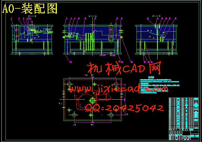
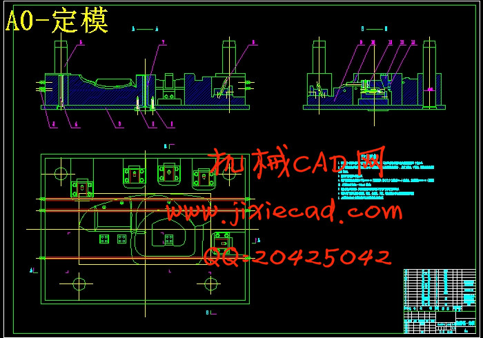
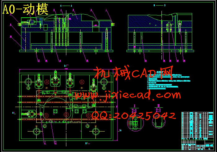
塑料工业的飞速发展,对注塑模具的设计与生产提出了质量好、制造精度高、研发周期短等越来越高的要求,能否适应这种需求已成为模具生产企业发展的关键因素。CAD/CAE/CAM技术的应用对我国模具工业的发展起到了重要的推动作用。本文介绍了塑件松花江P-L型组合仪表罩的成型工艺,及模具成型结构对塑件质量的影响,总装结构的设计、模具成型部分、顶出系统和浇注系统的设计。通过对模具结构方案、模具工作过程以及加工注意事项的详细分析与论述,力图让读者了解注射模的设计程序。通过思考,采用延迟开模侧抽及组合传动器方式,合理解决了动、定模上都有侧向抽芯及整体式传动器致使开摸行程过大的问题。关键词:CAD/CAE/CAM 注射模 侧抽芯机构 延迟开模
Abstract
Some higher demands such as high quality, high precision, short time of R&D and so on were put forward since the rapid development of plasticin dustry, whether they can adapt to these requirements has becoming an important factor for the development of molding producer. The application of CAD/CAE/CAM greatly promote the development of molding industry in our count Introduce plastic molding technique of the Songhua River P-L type shapingcraft in this paper ,and give mould shaping structural influence on moulding a quality, assembly design , mould shaping part , carry system of producing and pour the systematic design of structure. Through to particularly analyzing and discussing the mold’s plans and structures, working process and processing notices, try hard to let reader understand that inject designing program of the mold. Through thinking deeply, of working principle adopt delay make mould side release and make hammer mechanism actuator way up, reasonably solve , move , make mould have side direction smoke core and integral hammer mechanism actuator cause , turn on , touch journey too big problem rationally.
Key Words: CAD/CAE/CAM Core-pulling structure Injection mold Retards the mold
目 录
Abstract Ⅱ
第1章 绪论 1
1.1 选题的依据和意义 1
1.2 本课题在国内外的研究现状 2
1.2.1 国内现状 2
1.2.2 国外现状 4
1.2.3 存在问题和主要差距 5
1.3 本课题的发展展望 6
第2章 方案分析与论证 8
2.1 设计任务 8
2.2 塑件分析 8
2.3 设备的选择 9
2.4 设计依据 12
2.5 拟定模具结构方案 13
2.6 方案论证 14
第3章 模具总体结构设计 16
3.1 浇注系统设计 16
3.1.1 浇注系统的总体构成 16
3.1.2 主流道设计 16
3.1.3 分流道设计 18
3.1.4 浇口设计 19
3.1.5 冷料穴设计 20
3.1.6 分型面的设计 21
3.1.7 排气槽的设计 22
3.2 成型部分及零部件设计 23
3.2.1 型腔数的确定 23
3.2.2 一般凹凸模结构设计 23
3.2.3 成型零件工作尺寸 24
3.2.4 型腔壁厚计算 26
3.3 脱模机构设计 29
3.3.1 脱模机构的构成与功能 29
3.3.2 取出机构的方式设计 30
3.3.3 脱出机构设计原则 30
3.3.4 塑件的脱出机构设计 34
3.3.5 浇注系统凝料的脱出部件设计 38
3.3.6 拉料机构设计 39
3.4 侧向抽芯及合模导向机构设计 40
3.4.1 侧向抽芯机构设计 40
3.4.2 合模导向机构设计 46
3.5 冷却系统设计 49
3.5.1 冷却装置设计分析 50
3.5.2 冷却装置的理论计算 50
3.5.3 冷却回路的布置 53
第4章 模体设计与支承连接零件设计选择 56
4.1 模体结构设计 56
4.2 支承与连接零件 58
4.2.1 支承件 58
4.2.2 连接零件 59
4.3 其他零件 60
设计小结 63
致谢 64
参考文献 65


