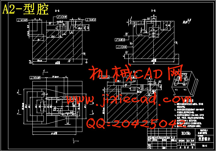
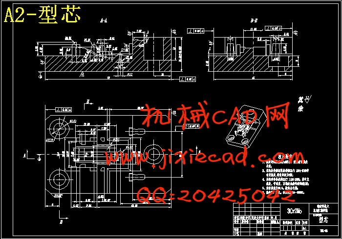
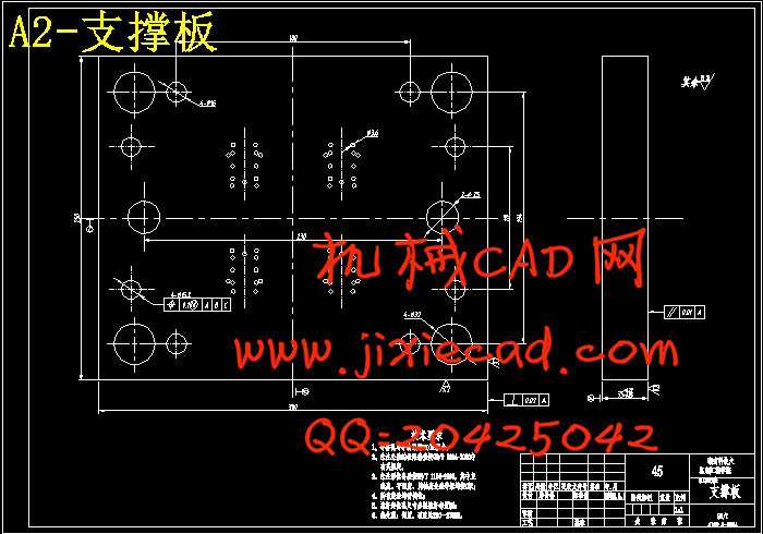
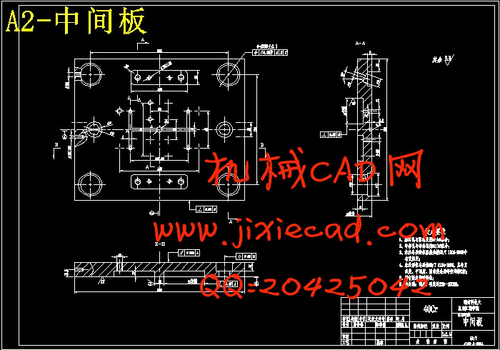
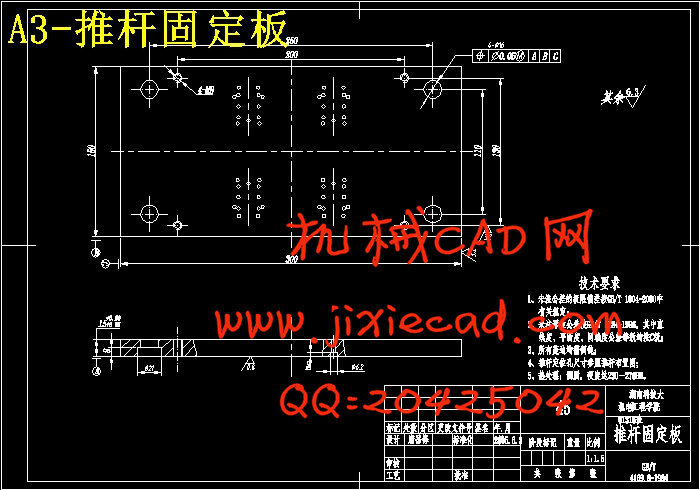
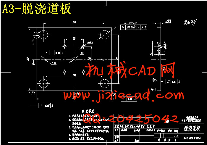
设计简介
塑料挂钩座注射模具设计摘要
注射模在机械、电子、航天航空、生物等领域及日用品的生产中得到了越来越广泛的应用,但我国的塑料成形模具设计整体水平还较低,跟发达国家有很大的差距,主要表现在:模具零件变形大、溢边毛刺大、表面质量差、模具型腔冲蚀和腐蚀严重、模具排气不畅和型腔易损等。目前,我国的注射成型发展方向主要为提高大型、精密、复杂、长寿命模具的设计制造水平及CAD/CAE/CAM技术的应用范围。
本设计的课题是塑料挂钩座注射模具设计,塑件结构复杂,尺寸精度要求较高,模具设计具有一定的难度。设计内容分为以下三个方面:注射可行性分析、模具总体设计和模具零部件设计。整个设计过程主要借助PRO/ENGINEER(以下简称PRO/E)、MoldFlow等软件完成。
该模具设计的过程为:
(1) 对塑件实体进行测绘,同时在PRO/E中创建其3D模型,并用PRO/E的模型分析功能对其进行初步分析和计算;
(2) 拟定型腔布局并选择合适的注射机;
(3) 利用PRO/E的模具模块完成模具的模仁设计和浇注系统设计,在设计浇注系统时,运用MoldFlow软件对塑件进行了最佳浇口位置分析和注射模流分析及模拟;
(4) 用PRO/E注塑模设计专家(简称EMX)进行模架和模具各零部件的设计。
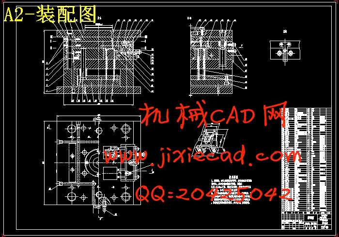
本设计的最大特点是运用先进的设计理念,在3D实体模型环境下完成整个模具设计过程。从零件建模,到模具结构设计,以及最后的工程出图,均通过PRO/E软件完成;并且在设计过程中充分利用了PRO/E、MoldFlow的分析功能,进行了如浇注系统分析、注射模拟、开模动作检测、干涉检测等工作,以设计出最为合理的模具结构。此外,设计中大部分分析计算都依靠设计软件进行,手工需要完成的只是模具的结构形式选择及计算校核,从而把设计工作从以往复杂繁琐的计算过程中解放出来,借助于EMX,大大缩短了模具设计花费在创建、定制和细化模架部件以及模具组件上的时间,并且其3D 实体模型也随着设计零件的更改而自动更新,从而使设计周期大为缩短,较好的保证了该模具的设计水平。本设计较好的实现了利用先进CAD/CAE/CAM技术对该复杂、精密塑件的设计。
关键词:塑料;挂钩座;注射模;Pro/Engineer;MoldFlow
The abstract of designing plastic pothook injection mould
The injection mould has been more and more widely used in the field of machine, electronics, aviation, biology and commodity. But the technology of designing injection mould in our country has a wide gap with developed countries due to comparatively low average lever. The gap is mainly reflected in the following aspects: the large deformity of the part, the great burr of side overflow, the lower surface quality, the serious erosion and cauterization of the mould, the bad exhaust of mould and the easily destroyed of the cavity and so on. At present, the direction of our injection mold is focus on improving the technology of large, exact, complex and long-life mould and widening the range of using the CAD/CAE/CAM.
The subject of the design is an injection mould for plastic pothook, as the configuration of the plastic is complex, and the precision of the dimension is high required, the design of the mould is difficult in some degree. The content of the design can be divided into three parts: the analysis of the injection possibility, the whole design of the mould and the design of the parts, the process have been finished chiefly with the help of software Pro/Engineer.
The general processes of the design is: firstly, survey and draw the plastic, establish it’s 3D model by PRO/E; then primarily analysis and figure up it using the analytic function of PRO/E; then sketch the draft of the layout of cavity and choose an equal injection machine; next, making use of PRO/E’s module to complete the design of core and cavity as well as molding system, on which, software MoldFlow is used to do the analysis of the best gate location and the analysis and simulation of fluid; at last, use Expert Moldbase Extension of PRO/E to execution the designing of the mold-base and every part of the mould.
The most conspicuous feature of the design is that the whole process is done in the environment of 3D model, which is conduct by the advanced theory. The software POR/E completes the work from modeling to the design of construction, and the last draw for engineering. During the process, the analytic function of PRO/E、MoldFlow have been fully used to do the work, such as: Analysis of molding system, injection simulation, the testing of mold opening and interference and so on, in order to make the most rational mould. In addition, most analysis and count are finished by design software automatically, therefore, what left to be done by hand are only selecting the form of the mould、 calculate and check the result. In which condition, the fussy compute process can be avoided, and the time spent on creating, ordering and simplifying the parts and component part can be largely shortened with the help of EMX. The 3D model can renew itself automatically as the change of the design parts, therefore, the design circle can greatly be shortened and the mould quality can be better secured.
Key words: plastic; pothook; injection mould; Pro/Engineer; MoldFlow
目录
前言....................................................................................Ⅰ
设计说明书.............................................................................1
第一章 产品分析.......................................................................1
1.1 塑件分析.......................................................................1
1.2 塑件原材料分析.................................................................2
第二章 拟定型腔布局...................................................................4
2.1 型腔..........................................................................4
2.2 型腔数目的确定.................................................................4
2.3 型腔排布......................................................................5
第三章 塑件相关计算及注塑机的选择.....................................................6
3.1 塑件相关计算...................................................................6
3.2 注塑机选择及注射工艺参数确定...................................................7
第四章 分型面设计.....................................................................9
4.1 分型面设计原则.................................................................9
4.2 分型面设计.....................................................................9
第五章 浇注系统设计...................................................................10
5.1 总体设计.......................................................................10
5.2 主流道设计.....................................................................11
5.3 分流道设计.....................................................................11
5.4 进料口设计.....................................................................13
5.5 冷料穴的设计...................................................................14
5.6 浇口套及定位圈的设计...........................................................14
5.7 塑件模流分析...................................................................14
第六章 模架选用及注射参数校核.........................................................20
6.1 模架...........................................................................20
6.2 开模行程校核...................................................................21
第七章 成型零部件设计.................................................................22
7.1 成型零件的材料选择.............................................................22
7.2 成型零件结构设计...............................................................22
第八章 侧向分型抽芯机构设计...........................................................28
8.1 侧向分型抽芯机构类型选择.......................................................28
8.2 抽芯距确定与抽芯力计算.........................................................28
8.3 斜导柱分型与抽芯机构零部件设计.................................................29
第九章 合模导向机构设计...............................................................34
9.1 导向机构.......................................................................34
9.2 定位装置.......................................................................36
第十章 脱模机构设计...................................................................37
10.1 脱模装置......................................................................37
10.2 推出机构设计..................................................................38
10.3 拉料机构......................................................................40
第十一章 冷却及排气系统设计...........................................................42
11.1 冷却系统......................................................................42
11.2 排气机构......................................................................44
第十二章 模具总体结构.................................................................45
结束语..................................................................................48
致谢....................................................................................49
参考文献...............................................................................50


