设计简介
摘要
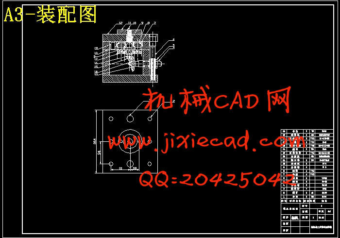
本课题主要是针对圆盖的注塑模具设计,该圆盖材料为改性PS,是工业生产中常见的一种保护盖产品。通过对塑件进行工艺的分析和比较,最终设计出一副注塑模。该课题从产品结构工艺性,具体模具结构出发,对模具的浇注系统、模具成型部分的结构、侧抽机构、顶出系统、冷却系统、注塑机的选择及有关参数的校核都有详细的设计,同时并简单的编制了模具的加工工艺。通过整个设计过程表明该模具能够达到此塑件所要求的加工工艺。根据题目设计的主要任务是圆盖注塑模具的设计,也就是设计一副注塑模具来生产塑件产品,以实现自动化提高产量。针对塑件的具体结构,该模具是点浇口的双分型面注射模具。
在现代的模具设计生产中,通常运用UG软件进行产品的3D图形设计,UGMoldWizard 是 UG 系统的一个独立的智能化设计注射模具的模块,按照注射模具设计过程的一般顺序来实现模具设计的整个过程。利用UG分析中的塑模部件验证对制件分析,并设置脱模方向及型芯和型腔区域。依次利用UG注塑模向导中的模具CSYS、收缩率、工件、型腔布局、分型、模架标准件、浇口流道和冷却等功能设计三维模具。并运用 UGMoldWizard 检验制件构的合理性,以及注射模具结构设计的可行性。最后由三维图直接生成二维图。
关键词:注塑模 圆盖 侧抽机构
ABSTRACT
The main topic covered for a round of injection mold design, the materials for Modified PS, is commonly found in industrial production of a protective cover products. Through the process of plastic parts for analysis and comparison, the final design of an injection mold. The product mix from technology issues, and specific mold structure of the casting mold system, mold forming part of the structure, side pumped body, top of the system, cooling system, the choice of injection molding machine and related calibration parameters are detailed design, at the same time and developed a simple process dies. Through the entire design process that the mold can be achieved by the plastic parts processing
knowledge-embedded theory to realize thewholemold designing process in a normal order of injectionmold designing process.First,mold components in the UG-validation analysis on the parts,and set the parting direction and the core and cavity region.Then,followed by the use of the Wizard of UG injection mold mold CSYS, the contraction rate of the workpiece, cavity layout, typing, mold standard parts, gate runner and cooling functions to design three-dimensional mold.and use the UGMoldWizard to check the production the accuracy is with high characteristics of efficiency. Finally,three-dimensional mold directly generate two-dimensional diagram.
Key words: Injection mold ;round cap ;side pumped body
目 录
摘要 I
ABSTRACT I
前 言 1
第1章 塑料成型制件的工艺性 1
1.1 制件原料的工艺性 1
1.2 制件的结构工艺性 2
第2章 初步选择注射机 3
2.1 成型前的准备 3
2.2 制品PS的注塑成型参数 3
2.3 塑件的形状估算其体积和质量 3
2.4 确定型腔数量 3
2.5 注射机有关参数 4
2.6 分型面选择 4
第3章 浇注系统 5
3.1 主流道的设计 5
3.2定位圈 6
3.3 分流道设计 6
3.4 浇口设计 6
3.5 流动比的校核 7
3.6 排溢系统 7
第4章 成型零件设计 8
4.1 凹模 8
4.2 凸模和滑块 8
4.3 型腔、型芯径向尺寸 9
4.4 型腔深度和型芯高度尺寸 9
4.5 凹模侧壁厚度和底板厚度的计算 10
4.6 合模导向结构机构设计 11
4.7 推出机构的复位 12
4.8 二级推出机构 12
4.9 侧向分型与抽芯机构设计 13
4.10 导滑槽设计 14
4.11 模架专用零件选取 14
4.12 推出行程的校核 16
4.13注射机有关参数校核和最终选择 17
第5章 冷却系统设计 20
第6章 UG模具设计 22
6.1 制件分析 22
6.2 UG模具设计 22
第7章 模具主要零件图及加工工艺规程 23
第8章 模具安装与调试 25
8.1 模具的安装 25第4章 成型零件设计 8
4.1 凹模 8
4.2 凸模和滑块 8
4.3 型腔、型芯径向尺寸 9
4.4 型腔深度和型芯高度尺寸 9
4.5 凹模侧壁厚度和底板厚度的计算 10
4.6 合模导向结构机构设计 11
4.7 推出机构的复位 12
4.8 二级推出机构 12
4.9 侧向分型与抽芯机构设计 13
4.10 导滑槽设计 14
4.11 模架专用零件选取 14
4.12 推出行程的校核 16
4.13注射机有关参数校核和最终选择 17
第5章 冷却系统设计 20
第6章 UG模具设计 22
6.1 制件分析 22
6.2 UG模具设计 22
第7章 模具主要零件图及加工工艺规程 23
第8章 模具安装与调试 25
8.2 模具的调试 25
第9章 模具工作过程 26
结 论 27
参考文献 28
致 谢 29


