设计简介
HFJ6371型车侧围装饰板卡扣的注射模设计
摘 要
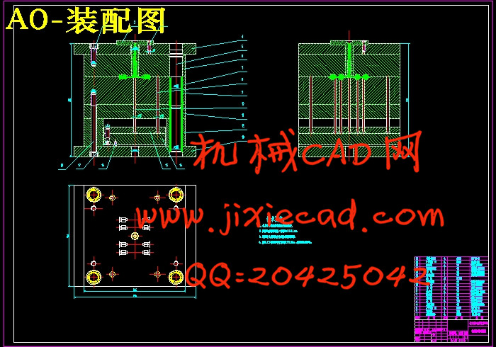
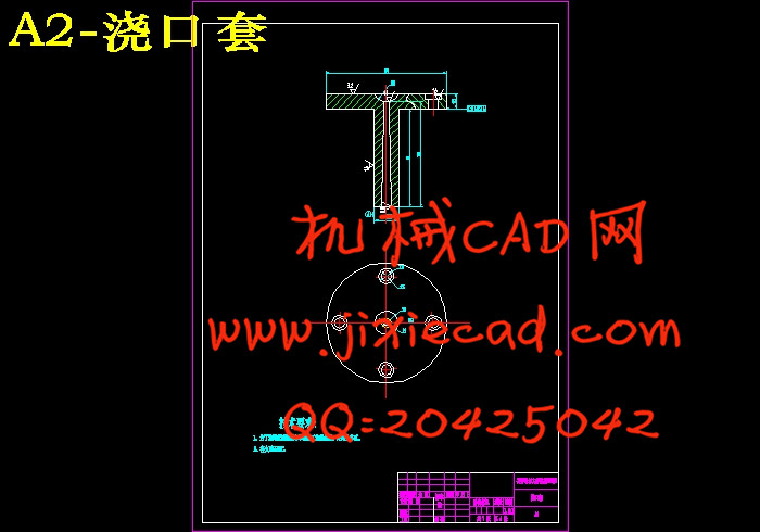
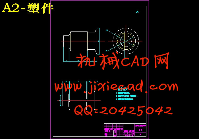
当今,随着世界经济的迅猛发展与人民的生活水平的普遍提高,汽车也越来越多的进入了普通家庭,因此带动了汽车工业的发展。而汽车业要实现高效率生产,模具是一个重要环节。用注塑模具来生产汽车饰品,不仅外表美观,而且经济实用,成本低。因此,注塑模设计的优劣与整个汽车工业的发展有着密切的联系。而CAD软件在模具设计中对模具设计方案进行分析和模拟来代替实际的试模,预测设计中潜在的干涉与缺陷等问题。本设计中,论述了HFJ6371型车侧围装饰板卡扣的注射模设计过程,同时也论述了应用CAD软件进行二维实体建模,并对其进行可行性分析和工艺性分析,然后利用软件设计出浇注系统和各种成型零件,最后根据成型特点和生产要求生成标准模架的整个过程。在设计中,由于零件结构尺寸较小,要保证零件质量,需采用一模多(八)腔结构。且应用点浇口结构,以便有利于成型。
关键词:塑料注塑模;装饰板卡扣;CAD;点浇口
Abstract
Today, with the rapid development of world economy and generally improve the living standards of people, cars are more and more into the average family, so bring the automobile industry. The automotive industry to achieve high efficiency, mold is an important part. Injection mold used to produce automobile accessories, not only looks beautiful, but also economical and practical, low cost. Therefore, the merits of injection mold design and development of the auto industry closely. And CAD software design of the mold in the mold design analysis and simulation to replace actual tryout, forecasting the potential to interfere with the design flaws and other issues.This design, the Model Side discussed HFJ6371 board deduction of injection mold decoration design process, but also discusses the application of CAD-D solid modeling software, and its feasibility analysis and process analysis, and then use software design the gating system and a variety of molded parts, and finally forming characteristics and production requirements under the standard mold of the entire build process. In the design, structure size as small parts, to ensure part quality, requires the use of a multi-cavity mold. And the application point of the gate structure, in order to facilitate molding.
Keywords:Plastic injection mold;Decorative board buckle; CAD; point gate
目 录
摘要 I
Abstract II
第1章 绪论 1
1.1 汽车行业的模具发展概况 1
1.2 模具行业在国内外的研究现状 2
1.3 CAD软件在模具行业的应用 2
1.4 选题的依据和意义 3
1.5 设计的难点 4
第2章 塑件分析与注射机的选用 5
2.1 塑件分析 5
2.1.1 塑件外形分析 5
2.1.2 确定塑件的批量 5
2.1.3 塑件的尺寸、表面粗糙度 6
2.1.4 塑件所用塑料名称、性能及工艺参数 6
2.2 设备的选择 7
2.2.1 注塑机选择的依据 7
第3章 模具总体结构设计 10
3.1 拟定模具结构方案 10
3.2 浇注系统 10
3.2.1 浇注系统的总体构成 10
3.2.2 主流道设计 11
3.2.3 分流道设计 13
3.2.4 浇口设计 14
3.2.5 冷料穴设计 15
3.3 成型部分及零部件 16
3.3.1 分型面的设计 16
3.3.2 一般凹凸模结构设计 17
3.3.3 成型零件的工作尺寸计算 17
3.3.4 型腔壁厚计算 19
3.4 脱模机构 22
3.4.1 脱模机构的构成与功能 22
3.4.2 取出机构的设计 22
3.4.3 脱出机构设计原则 22
3.4.4 塑件的脱出机构设计 24
3.4.5 温度调节系统设计 28
第4章 模架设计 29
4.1 模架概述 29
4.2 模架结构设计 29
4.2.1 定模板 30
4.2.2 动模板 30
4.2.3 定模座板 31
4.2.4 动模座板 32
4.2.5 动模垫板 32
4.2.6 垫块 33
4.2.7 推板与顶杆固定板 34
4.3 导向零件 34
4.3.1 导向结构的总体设计 34
4.4 模具的运动过程 36
结论 38
参考文献 39
致谢 40


