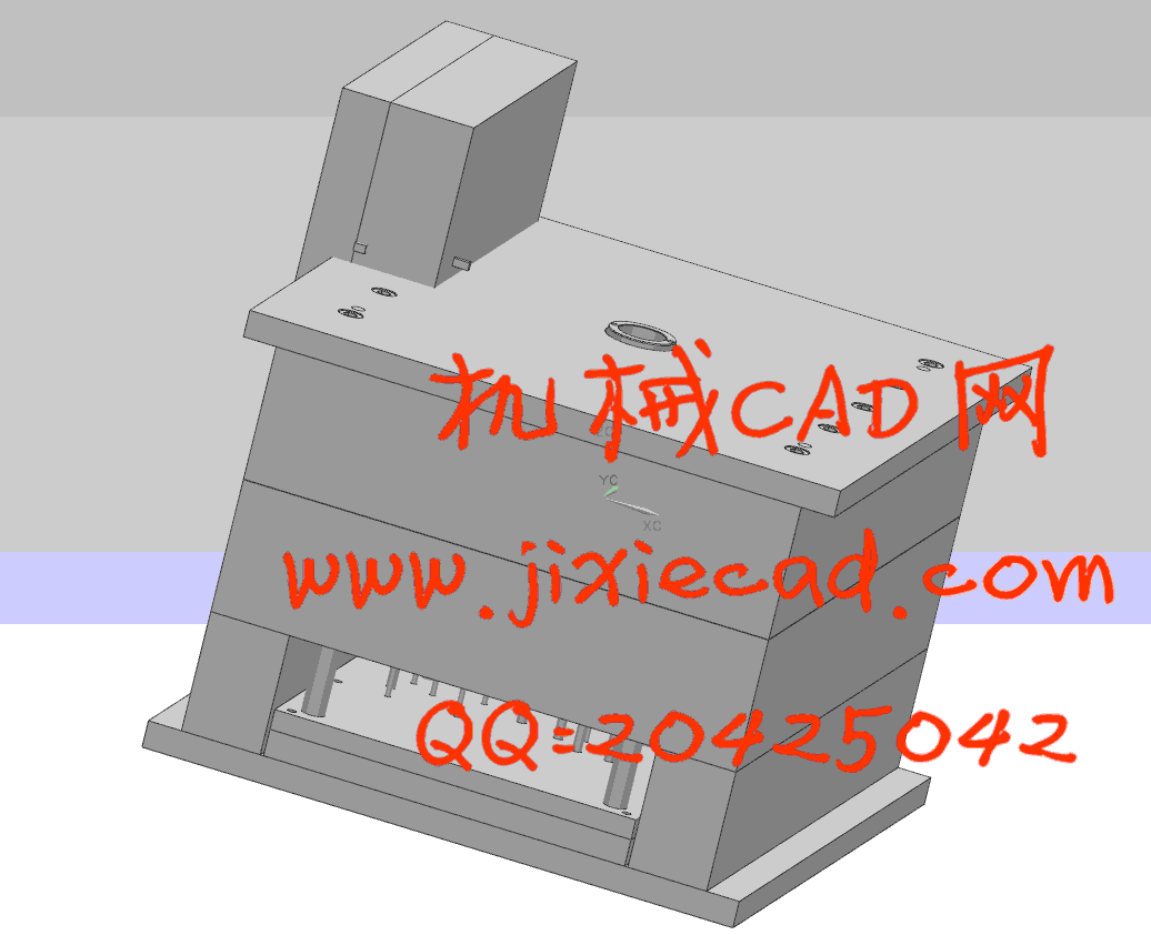
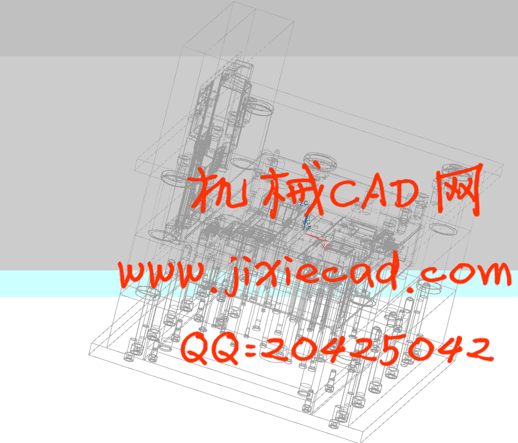
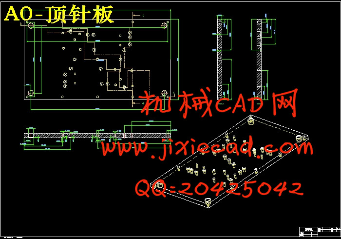
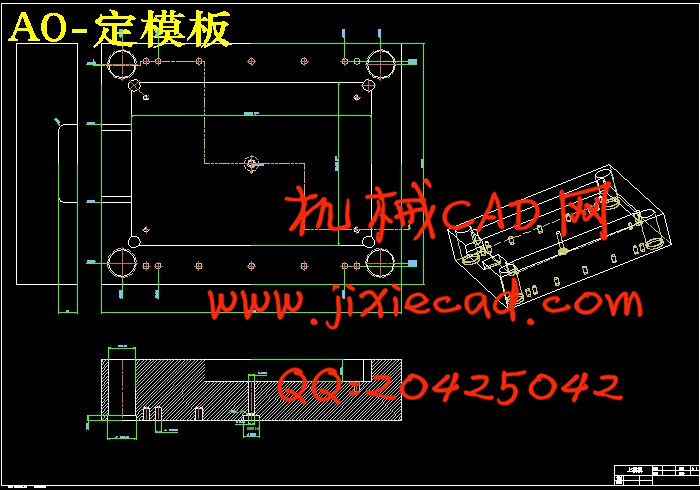
设计简介
摘要
模具是现代工业的重要装备,随着工业生产的飞速发展,新产品更新速度不断加快,对模具设计与制造业提出了更高的标准,即要求在保证生产质量的同时,缩短研发周期、降低生产成本。
Pro/MOLDESIGN是Pro/ENGINEER的一个选用模块,提供给使用者仿真模具设计过程所需的工具。这个模块接受实体模型来创建模具组件,且这些模具组件必然是实体零件,可以应用在许多其它的Pro/ENGINEER模块,例如零件,装配,出图及制造等模块。由于系统的参数化特性,当设计模型被修改时系统将迅速更新,将修改反映到相关的模具组件上。
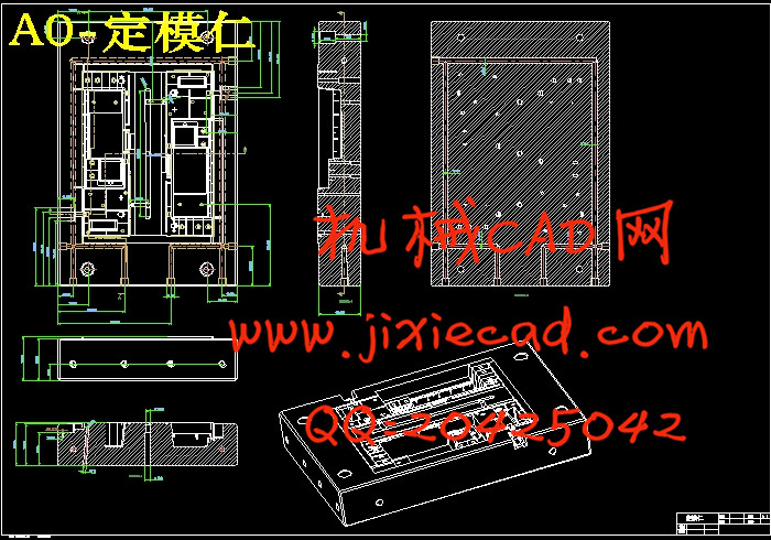
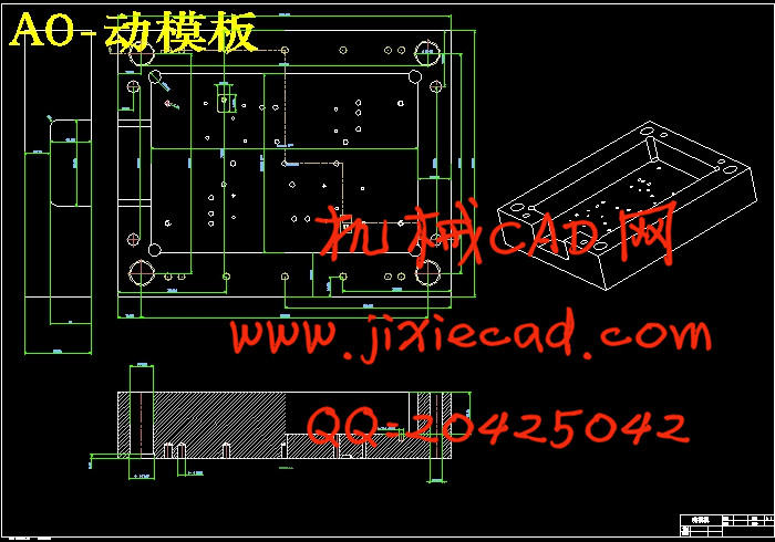
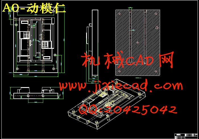
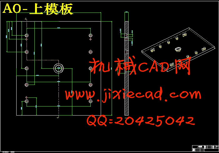
本文对电脑显示器后壳模具的技术要求和工艺结构进行了分析,根据分析结果选用注塑机和注塑工艺,从而确定显示器后壳注塑模设计思路及方案,最后进行注塑模结构设计与计算。在设计过程中运用Pro/E、AutoCAD软件,首先在Pro/E模具设计模块中做出分型面,利用分型面得出动、定模,再将型腔及所选的标准模架导入装配模块,从总体到个体的设计思路,设计出每个单一零件,最后导入工程图中并转化到AutoCAD软件中进行标注,从而得出完整的设计结果。
关键词 注射模;模具设计;分型面;模架
Abstract
The mould is one of the most important technology accoutrement in the modern industry, the new products which are end to end emerging are calling for the mould research needs to improve the speed and manufacturing quality, or in other words the preparation work is finished by minimum cyclic and lowest final cost.
The Pro/MOLDESGN,which is the module of Pro/ENGINEER offers the user the designing process. The module can accept entity mold to create the molding part, far more the entity mold is component naturalism, and The component can also be used in many other Pro/ENGINEER module in many other Pro/ENGINEER module. For example, the component, assemblage, drawing practice, manufacture and so on. When the design mold is modified, the system is updating rapidly, and adding the modified mold to the mold mould, which is contacted to original mould.
Most of the time should be put on technical requirement and construction in this thesis. After all, We selected the model numbered the injection mold of machine as inspected by the analysis result, and studied out the injection technology, and most of all defining the design programming of the injection mold of the back cover of the computer’ indicator. Finally, designing and calculating the construction of injection mold. We use many tools such as Pro/E software and AutoCAD software in all the entire process. The moving mould and solid mould be obtained by the mould joint, and then decanting the impression with standard die carrier into the assembly section. With the consciousness by designing from population to individual, and then drew out all the unity components and decanted the component into the schedule drawing and inverted into Auto CAD in the end. So we can get out the perfect designing theory.
Keywords injection mould mould design parting surface die carrier
目 录
1 绪论 1
2 注塑模具设计要求 5
2.1 塑件分析 5
2.2 塑件的成型性能 5
2.3 注塑工艺路线和设备 7
2.4 模具类型 7
2.5 模具设计 7
3 模具设计流程 8
3.1 设计依据 8
3.2 设计程序 8
4 注塑材料分析与选择 9
4.1 主材料分析 9
4.1.1 材料分析 9
4.1.2 塑料的成分 9
4.1.3 塑料的性能特点 13
4.2 注射模的塑料选择 13
4.2.1 ABS材料的特点 14
4.2.2 ABS材料成型特性 14
5 注射机的选用 15
5.1 注射机的结构类型 15
5.2 主要技术参数 16
5.3 技术规格及特性 16
5.4 注射机选择 17
6 分型面确定与模具设计 18
6.1 分型面的确定 18
6.1.1 分型面的概述 18
7 模架结构的设计 20
7.1 标准模架选用 21
7.2 标准零件的设计 21
7.2.1 结构支撑件设计 22
8 浇注系统和冷却系统设计 24
8.1 浇注系统 25
8.1.1 浇注系统的形式 26
8.1.2 浇注系统的设计原则 26
8.1.3 基于UG浇口位置分析 26
8.1.4 手机面板浇注系统设计 27
8.1.5 UG浇注系统设计效果图 27
8.2 冷却系统 28
8.2.1 冷却系统的作用 28
8.2.2 冷却效率 28
8.2.3 手机面壳模具冷却系统设计 29
9 模具相关校核计算 31
9.1 注塑机参数的校核 31
9.1.1 注射量的校核 31
9.1.2 锁模力的校核 32
9.1.3 最大注射压力的校核 32
9.1.4 开模行程的校核 32
9.2 注塑机安装模具部分的尺寸校核 33
9.2.1 喷嘴尺寸 33
9.2.2 定位环尺寸 33
9.2.3 模具厚度 33
9.3 模具的长度与宽度 34
9.3.1 开模行程校核 34
9.3.2 顶出装置的校核 34
9.4 成型零部件的设计计算 35
9.4.1 成型零部件尺寸分析 35
9.4.2 注射模相关强度计算 34
9.5 冷料穴的设计 36
9.6 模具温度调节系统 36
9.6.1 温度调节对塑件的影响 36
9.6.2 温度调节对生产力的影响 37
9.7 合模导向和定位机构 37
9.8 加工成本 37
结论 38
致谢 39
参考文献 40


